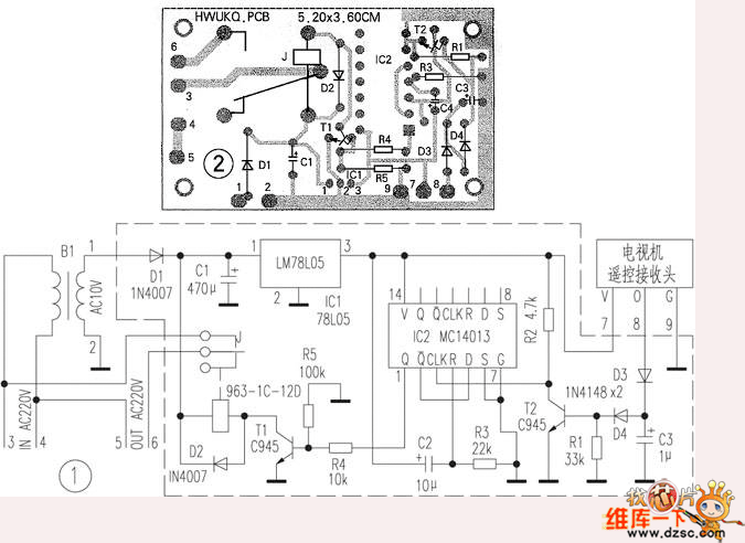
Not long ago, a YK-1D wireless remote control power socket used by the author was damaged, so an infrared remote power socket that can be controlled by a TV or a VCD remote controller was fabricated by using its casing and power transformer.
Socket circuit. The circuit adopts an infrared receiving head with integrated receiving, amplifying and demodulating. The relay triggering driving circuit uses a double D flip-flop MC14013. This circuit uses only one of them and is connected to a bistable form. D and Q are connected, R The S terminal is grounded. The R3 and C2 resistor-capacitor networks connected to the R terminal function as a power-on reset to ensure that the outlet is in the "off" state when the power is turned off and then called.
In normal times, since the output end of the receiving head is about 2. 2V high level, T2 is in the on state, the trigger input terminal (CLK) of the bistable circuit is low level, the Q terminal outputs low level, T1 is cut off, the relay J does not work, the socket has no 220V output. Press any button on the remote control, the receiving head receives the signal from the remote control, and outputs the demodulated pulse signal from the output terminal. At this time, the voltage at the output terminal decreases, and T2 is turned off, which is equivalent to giving the CLK terminal an instantaneous high level. The Q terminal outputs a high level, T1 is turned on, the relay J works, its normally open contact is sucked, the socket outputs 220V voltage, and then the remote controller is pressed, and the socket is de-energized.
Printed board diagram. If you find that the anti-interference ability is poor during production, you can solve the problem by: the power transformer and the integrated receiving head should not be too close to avoid interference. The connection between the signal output end of the receiving head and the circuit board is shielded, and a power of 47-100 μF is applied between the power supply and the ground of the receiving head.

Any QI enabled device like iPhone X/ 8/8Plus, Galaxy, Samsung S7,S7 Edge, S6,S6 Edge, Nexus 4/5/6 (NOTE: Other device have no wireless charging function except putting on extra receivers.)
Starts the moment you place down any Qi-enabled device or device equipped with a Qi-compatible cover. No cables or USB interface required. Input: AT LEAST 5V/2A; Output: 5V/1A
Wireless Charger,Universal Wireless Charger,Portable Wireless Charger,Mobile Wireless Charger
Shenzhen Waweis Technology Co., Ltd. , https://www.laptopsasdapter.com