This article will discuss various power supply topologies, especially when converting Li-Ion battery voltages to 3.3V voltage rails (the supply voltage for most portable devices). This article also explains the different applications of buck/boost converters and explains why buck/boost converter solutions need to be “tailor-madeâ€.
As can be seen from Figure 1, the design of converting a Li-Ion battery voltage to a 3.3V voltage rail is challenging. In the case of full charge, the typical lithium ion battery discharge curve has a starting voltage of 4.2V. The starting point of the X axis is "-5 minutes", and the corresponding voltage is the open circuit voltage when the battery is fully charged. At "0 minutes", the battery is connected to the load, and the voltage begins to drop due to the internal impedance and the protection circuit. The battery voltage slowly drops to about 3.4V, and then the voltage begins to drop rapidly because the discharge cycle is nearing the end. To take full advantage of the battery's stored power, the 3.3V rail requires a step-down converter for most of the discharge cycle and a boost converter for the remainder of the discharge cycle.
Figure 1:1650mA-hr 18650 lithium-ion battery discharge curve.
The problem of how lithium-ion battery voltages effectively generate 3.3V voltage rails has been around for a long time, and the solutions are varied. This article discusses several common solutions, including cascading buck and boost, buck/boost, buck, and LDO power topologies, and discusses the pros and cons of each design and the measurement and comparison of system run time.
Cascaded Buck and Boost Converter Solutions
The cascaded buck and boost converters consist of two separate and separate converters, a buck converter and a boost converter. The buck converter stabilizes the voltage at a medium voltage (such as 1.8V), while the boost converter boosts the medium voltage to 3.3V. This architecture is well suited for systems that require lower voltage rails because of the 100% battery power utilization. However, due to the two-stage conversion mechanism, this is not the best solution from the perspective of efficiency.
The effective power conversion efficiency is the product of the buck regulator efficiency and the boost regulator efficiency. Under the above voltage conditions, the typical efficiency values ​​of the buck and boost converters are both 90%, so the effective power conversion efficiency of the 3.3V converter is 90% × 90% = 81%. Since the architecture consists of two independent converters, the number of components and the size of the system are increased, which is difficult to apply in small portable products, but also increases the cost.
Independent Buck Converter Solution
The use of a buck converter also converts the Li-Ion battery voltage to 3.3V, but this solution is often overlooked and not widely used. The design engineer will generally abandon this solution after observing the battery discharge curve (shown in Figure 1) because the buck regulator cannot generate 3.3V from the battery full discharge curve (shown in Figure 1). Voltage rail. Many buck converters go into 100% duty cycle mode when the buck converter's input voltage drops close to the output voltage. Under this condition, the converter stops switching and outputs the input voltage directly. In 100% duty cycle mode, the output voltage is equal to the input voltage minus the voltage drop across the converter. The voltage drop is determined by the MOSFET on-resistance, the DC resistance of the output inductor, and the load current. This sets the minimum battery voltage that is still in regulation. Assuming the system considers the 3.3V rail to drop by 5%, it is still in regulation. , use the following equation to calculate the minimum battery voltage for system operation.
Vbattery_min=Vout_nom×0.95+(Rdson+RL)×Iout(1)
Among them: Vout_nom is the rated value of 3.3V, Rdson is the power MOSFET on-resistance, RL is the output inductor dc resistance, and Iout is the output current of the converter 3.3V.
When the battery voltage drops to Vbattery_min, the system must be turned off below the minimum tolerance to avoid running on the 3.3V rail and damaging the data. Even if the battery still has 5 to 15% of power remaining, the system may turn off. How much battery power remains before the system is turned off depends on various factors such as component resistance, load current, battery age and ambient temperature.
Most design engineers will abandon the use of a separate buck topology for this reason, but a careful study of the actual operating time of the system will reveal that the conversion efficiency of the standard buck/boost, cascade buck, and boost topology is lower than that of the individual. The voltage converter is much less efficient. Although these topologies make the most of battery power, they are much less efficient than buck converters. In many cases, the individual buck converters run longer than the other two topologies. Until 2005, the fully integrated buck converter was considered the best choice for generating a 3.3V rail.
Low Dropout Regulator Solutions
Another less common solution is the LDO. Similar to the “separate buck†solution, the LDO cannot fully utilize the full battery power because the input voltage is stable only when the input voltage is greater than the sum of the output voltage and the LDO voltage drop. Pressure effect. If the LDO voltage drop is 0.15V, then when the battery voltage is lower than 3.3V+0.15V=3.45V, the 3.3V output voltage begins to drop. Battery power that cannot be fully utilized with this solution is likely to be much more than a separate voltage drop solution. Despite these shortcomings, LDOs have advantages in certain circumstances.
The LDO solution is usually the smallest size, so it is ideal when the main system has strict space requirements. The cost of an LDO solution is usually the lowest, so it is ideal for low-cost applications. Many design engineers abandoned the solution because of LDO inefficiency, but after careful study, the efficiency in this application is good:
When the initial voltage of a fully charged lithium ion battery is 4.2V, the initial efficiency of the LDO is 78%, and its efficiency rises as the battery voltage decreases.
Male Pin Headers
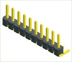
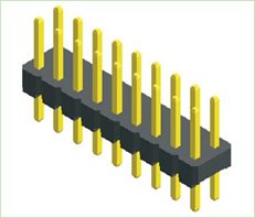
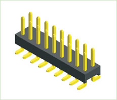
1.ANTENK MALE PIN HEADER Series in Headers are a full range headers in a variety of configurations including Single, Dual and Three rows, Straight or Right Angle in Thru-Hole or SMT mounting. Their close tolerance .025" sq. posts are smoothly finished and taper tipped to eliminate insertion damage to the PCB or mating connector. ANTENK Pin Headers can be easily cut into exact sizes as required. Options include stacked insulator versions and choice of tin, gold or selective gold plating.
Antenk Male Pin Headers Types By Pitch
0.8mm Male Header
1.0mm Male Header
1.27mm Male Header
2.0mm Male Header
2.54mm Male Header
Antenk Male Pin Headers Application
Antenk's Male Pin Header are widely used in electronic equipments,such as monitors ,electronic instruments,computer motherboards,program-controlled switchboards,LED,digital cameras,MP4 players,a variety of removable storage disks,cordless telephones,walkie-talkies,mobile phones,digital home appliances and electronic toys,high-speed train,aviation,communication station,Military and so on.


Male Pin Headers:
SPECIFICATIONS:
Current Rating: 0.75Amp
Insulation Resistance: 1000M ohms min
Contact Resistance: 20M ohms max
Dielectric Withstanding: AC500V
Operating Temperature: -65°C to +125°C
Contact Material: Brass
Insulator Material: PA6T,UL94V-0,Color:Black
Male Pin Headers,Pin Male Straight Box Header,Smd Pin Headers,Long Pin Male Header,Pin Header,Male PCB Connectors
ShenZhen Antenk Electronics Co,Ltd , https://www.antenk.com