The application of wireless sensor networks in intelligent transportation has great prospects. In road traffic, sensor networks have their own special network topology and band topology. Based on the characteristics of wireless sensor networks, this paper studies the easy-to-implement network routing protocols suitable for the ribbon topology.
1 Network structure and routing analysis
The limitations of the existing routing technology make it not directly applicable to sensor networks, and the networking and communication protocols designed for mobile Ad Hoc networks are generally not suitable for sensor networks. One of the important reasons is that its scalability requirements are different. In terms of mobility of mobile Ad Hoc networks relative to nodes, scalability problems are not very prominent; while sensor networks require support for large-scale networks, the mobility of nodes is weak or even not , The main problem becomes how to extend the survival time of the network. This determines that the two networks have different optimization goals. Therefore, it is necessary to study the sensor network routing protocol according to the characteristics of traffic information data collection and transmission in the traffic demonstration project, and focus on solving the problems of improving scalability, low power consumption, and adapting to changes in network topology.
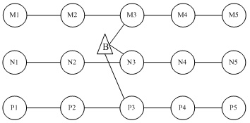
Band topology network, as shown in Figure 1, the network is a tree chain structure, borrowing the concept of hierarchical network [1], the network is divided into two layers, the bottom layer is the sensor node to collect environmental parameters, the upper layer is the network's convergence node, or It is the management center of the small network in the region, and the information gathered in the region is transmitted to the higher layer network after data fusion. Due to the particularity of the ribbon network, the underlying network is divided into multiple clusters according to geographic location. The reasonable cluster structure is to cluster according to the direction of the chain, and the cluster head is not specified. Therefore, the underlying network can also be called a cluster-less hierarchy The internet. Under normal circumstances, the nodes between different clusters do not communicate with each other, and the collected information of all nodes is transmitted to the upper-layer network through the nodes of the cluster.

Figure 1 Network topology diagram of the band structure
As shown in Figure 1, the bottom layer is divided into three clusters of M, N, and P, and the number of members in the cluster can be arbitrarily expanded in the banded area. The upper-layer network node B can move at high speed [2].
Such a network with a ribbon structure has its own characteristics in the establishment and maintenance of routes. Since the bottom node does not need to move, or moves slowly in a certain range, its purpose is to pass the collected information to the node that moves above. Therefore, the underlying network routing uses a table-driven approach. The upper network node establishes the route of the entire network, but the task of maintaining the route is completed by the local node.
2 Ribbon network structure routing protocol
2.1 Route establishment
The idea of ​​the route establishment process is that the upper node broadcasts the route request packet RREQ in the whole network. After receiving the RREQ, the lower node updates the neighbor list and the routing table, and then forwards the RREQ by broadcast, but only forwards RREQ in the same cluster; local nodes establish routes in the same cluster, but the maintained neighbor list includes neighbor information of the entire network to record network connectivity.
Borrow the RREQ packet format in the AODV routing protocol, and define the protocol RREQ format as shown in Table 1 [3, 4].

Among them, the packet type: used to indicate that the data packet is a RREQ packet, a broadcast packet; source address: the address of the node that initiated the RREQ, which should be the address of the upper-layer network node; hop count: the number of hops that the source node took to the node that received the RREQ packet Number of segments; broadcast ID: the serial number maintained by the source node, used to uniquely identify the RREQ packet.

Among them, the destination node: record the destination node address, which should be the address of the upper-layer network node; routing status: whether the route is valid; next hop: the address of the next hop node from the local node to the destination node; route expiration time: the route is no longer valid Time.
According to the role of different nodes in the process of route establishment, the route establishment process is as follows:
1) Upper-layer mobile node: broadcast RREQ to the entire network to establish routes; receive data packets carrying information from nodes in each cluster. See node B in Figure 1. The unique ID RREQ is identified by the broadcast ID and source address sequence, which is used to judge whether the process receives duplicate RREQ packets
2) A node that can directly communicate with a mobile node: After receiving the RREQ, it first updates the neighbor list, then writes the next hop in the local routing table to B, and updates the routing table. As shown in Figure 1, M3, N3, and P3 are directly connected to B at this time, and are the exits of other nodes in the three clusters to access upper-layer nodes.

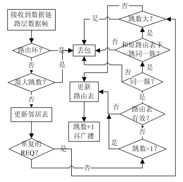
Figure 2 Local node establishment routing process
3) Other nodes in the underlying network: M3, N3, and P3 receive the RREQ of B. After updating the routing table, they also forward the RREQ in a broadcast manner. At this time, the nodes in different clusters will receive the forwarded RREQ, and use this information to update the local The neighbor list of nodes. For example, in Figure 1, N4 receives RREQ forwarded by N3, and may also receive RREQ forwarded by M3 and P3. N4 uses this information to update its neighbor list. However, N4 updates the routing table with the RREQ forwarded by the same cluster member. The next hop in the routing table is recorded as the N3 address, and then discards other received same RREQ packets. The RREQ is also forwarded again in a broadcast manner. The advantage of this processing is that RREQ is broadcast in the same cluster, that is, a route is established, and all neighbor nodes of the local node are recorded, including neighbor nodes in other clusters, and RREQ is effectively avoided in the entire network causing "broadcast storm" The problem. All other nodes are processed in the same way until the RREQ packet reaches the maximum network radius.
The process of route establishment is shown in the flow chart of Figure 2.
2.2 Route maintenance
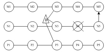
In a band topology, there are limited neighboring nodes in the same cluster. In most cases, only the left and right nodes are its neighbors. If a node is exhausted due to energy, the nodes in the cluster may be disconnected, which will affect the robustness of the network. And scalability, as shown in Figure 3, node N4 no longer has the function of a sensor node for some reason. The node to the right of N4 cannot transmit data to the destination node B according to the previously discovered route, so some measures must be taken to Maintain network connectivity. A node has neighbor nodes in other clusters at the same time, and can continue to transmit data packets with the help of nodes in other clusters.

Figure 3 Maintenance of routing in case of network failure
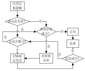
In view of the particularity of the ribbon topology, after finding the direction of the destination node (ie routing), the data packets are transmitted in the order of "relay", so the end-to-end response method is not used, but the point-to-point response is adopted. Reply, so that the node can know the status of the next node. When sending a data packet, if it can not receive the response packet of the next hop node, it will be sent again. If there is still no response, it is considered that the next hop is faulty. In the neighbor list, neighbor nodes in other clusters are selected as the next hop nodes, and the cluster nodes are responsible for transmitting data packets.
In Figure 3, after the right packet of N5 is forwarded to N5, since N5 does not receive the response from N4, N5 needs to select one of the neighbor list as the next hop. N5 neighbors), priority selection (pay attention to avoid routing rings), if not, select other neighbors in the cluster, N5 in the figure selects M5, N5 will successfully send the packet to the members of cluster M, cluster M is responsible for forwarding the packet To the destination node. At this time, the next hop field of the N5 routing table is changed to M5, and the route expiration time is the expiration time of the neighbor node M5, until N5 receives the RREQ update route forwarded by the nodes in the same cluster again. At the same time, N5 informs the upper layer network of N4 fault information in time.
The process of routing maintenance is shown in the flow chart of Figure 4.

Figure 4 Local node maintenance routing process
3 Application and practice of strip topology in road traffic
Wireless sensor networks can achieve reliable data transmission over long distances. The sensor nodes are self-organized into a network, which quickly forms a relatively stable network topology. Wireless sensor networks in road traffic are typical applications for ribbon networks. In road traffic, the wireless sensor network has the following functions: the sensor data is quickly and reliably transmitted to the user terminal; the topology changes with the position of the upper node; the network is turned off or a certain node is added, and the dynamic change of the network is strong; the unique number of the node , Summarize the sensor information in the upper layer; reproduce the change process of the network topology at the user terminal according to the information received by the upper network node; for example, distribute the sensor nodes along the sides of the road to collect road surface information, etc., the upper layer network can be independent Fast-moving car nodes, the car can receive the information from the underlying network as needed, so that the car can know the status of the road in front and behind in time and accurately. Cars can pass information to traffic control hollows through higher-level networks.
In the project, the radio frequency chip is CC1100, the frequency is 433MHz, and the maximum effective range is adjusted to about 150 meters. The processor selects LPC2210, and the operating system transplants the open code of μC / OSⅡ. At the same time, due to the special application environment of the project, the noise from the car has a serious impact, and the correctness of the data packet must be strictly controlled. Application practice shows that the routing protocol of this solution is simple and easy to implement and the routing cost is small.
Aiming at the particularity of the band topology of wireless sensor networks, a hierarchical network management method is proposed. The underlying network adopts a cluster-less clustering structure, so that the establishment and maintenance of network routes are easy to implement. The study of network routing protocols with a ribbon topology greatly promotes the application of sensor networks in road traffic. Change the current single technical means of road information collection. Data fusion processing of multiple traffic information collected by the sensor network improves the accuracy and reliability of road traffic information.
The author of this article is innovative. For the application of wireless sensor networks in road traffic, the network is divided into two levels according to its special strip topology, and an easy-to-implement clustering routing protocol without cluster heads is proposed, that is, the upper mobile node Establish a mechanism for routing and the maintenance of routing by the underlying nodes. This routing protocol has shown in road traffic applications that it is easy to implement, has low overhead, and is easy to maintain.
All In One Gaming PC is the best choice when you are looking higher level desktop type computer for heaver tasks, like engineering or architecture drawings, designing, 3D max, video or music editing, etc. What we do is Custom All In One Gaming PC, you can see Colorful All In One Gaming PC at this store, but the most welcome is white and black. Sometimes, clients may ask which is the Best All In One Gaming PC? 23.8 inch i7 or i5 11th generation All In One Gaming Desktop PC should beat it. Cause this configuration can finish more than 80% task for heavier jobs. Business All In One Computer and All In One Desktop Touch Screen is other two popular series. Multiple screens, cpu, storage optional. Except All In One PC, there are Education Laptop, Gaming Laptop, i7 16gb ram 4gb graphics laptop, Mini PC , all in one, etc.
Any other unique requirements, Just feel free to contact us and share your ideas, thus more matched details sended in 1-2working days. Will try our best to support you.
Of course, any we can do in China, also willing to do it for you.
All In One Gaming PC,Best All In One Gaming Pc,Colorful All In One Gaming Pc,Custom All In One Gaming Pc,All In One Gaming Desktop Pc
Henan Shuyi Electronics Co., Ltd. , https://www.shuyiaiopc.com