Near Field CommunicaTIon (NFC), also known as short-range wireless communication, is a short-range high-frequency wireless communication technology that allows non-contact point-to-point data transmission (within ten centimeters) to exchange data between electronic devices. . This technology evolved from contactless radio frequency identification (RFID) and is backward compatible with RFID. It is mainly used to provide M2M (Machine to Machine) communication in handheld devices such as mobile phones. Because near-field communication has natural security, NFC technology is considered to have great application prospects in the field of mobile payment. In recent years, due to the rapid growth of the functions and popularity of mobile phones, early e-wallets have been promoted. The evolution of NFC is taken from the specific frequency band of RFID. Since the market application of mobile phones enables NFC to obtain standard interfaces and platforms at a relatively fast time, this paper will briefly discuss the architecture and specifications of NFC.
NFC - Application:In the electronic payment system, the most complete solution currently applied to mobile phone systems is based on NFC, and related products are already circulating in the market. In addition to personal identification and electronic payment systems, NFC also has some attractive features in data transmission and exchange, such as data downloads for electronic posters (including admission volumes, exhibition information). In addition, NFC can also be used as a simplified function for pairing and inputting passwords for Bluetooth devices. If the user has a Bluetooth device with NFC load, NFC can be brought close to two sets of NFC-enabled Bluetooth devices, so that no need to search and input via Bluetooth. The password pairing process can be quickly linked. At present, South Korea has conducted multiple verifications in the bus payment system in cooperation with telecom operators, chip vendors and mobile phone manufacturers in Europe and the United States.
NFC - technical features:Like RFID, NFC information is also transmitted by electromagnetic induction coupling of the radio frequency portion of the spectrum, but there is still a big difference between the two. First of all, NFC is a wireless connection technology that provides easy, secure and fast communication. Its transmission range is smaller than that of RFID. The transmission range of RFID can reach several meters or even tens of meters, but because NFC adopts unique signal attenuation technology, Compared with RFID, NFC has the characteristics of close distance, high bandwidth and low energy consumption. Second, NFC is compatible with existing contactless smart card technology and has become the official standard supported by more and more major vendors. Once again, NFC is a close-range connection protocol that provides easy, secure, fast, and automatic communication between devices. Compared to other connections in the wireless world, NFC is a close-range, private communication method. Finally, RFID is more widely used in production, logistics, tracking, and asset management, while NFC plays a huge role in access control, public transportation, and mobile payment.
NFC, infrared and Bluetooth are both non-contact transmission methods. They have different technical characteristics and can be used for various purposes. The technology itself has no advantages and disadvantages.
The NFC mobile phone has a built-in NFC chip, which increases the bidirectional transmission of data than the RFID used only as a tag. This advancement makes it more suitable for electronic money payment; especially RFID can not achieve, mutual authentication and dynamic encryption and A one-time key (OTP) can be implemented on NFC. NFC technology supports a variety of applications, including mobile payments and transactions, peer-to-peer communications, and mobile information access. With NFC phones, people can connect to the entertainment services and transactions they want, from any location, at any time, through any device, to complete payments, get poster information, and more. The NFC device can be used as a contactless smart card, a smart card reader/writer terminal, and a device-to-device data transmission link. The application can be mainly divided into the following four basic types: for payment and ticket purchase, for electronic ticket, Used for smart media and for exchanging and transmitting data.
Comparison of NFC-related near-field communication technologiesCompared with traditional near-field communication, Near Field Communication (NFC) has natural security and rapid connection establishment. The specific comparison is as follows:
NFC Bluetooth Infrared
Network type point-to-point single point to multi point to point
Use distance ≤0.1m≤10m≤1m
Speed ​​106, 212, 424 kbps
Planning rate up to 868 kbps
721 kbps 115kbps2.1 Mbps~1.0 Mbps
Established time "0.1s6s0.5s
Security is available, hardware implementation is available, software implementation is not available, except when using IRFM
Communication mode active-active/passive active-active-active
Low cost
NFC - Architecture:The operating frequency of NFC is 13.56MHz, and the operating distance is about 10cm. The specification of NFC is taken from the frequency band of RFID 13.56MHz. The early use of this frequency band includes PhilipsMiFARE (ISO1443A), ISO1443B, ISO15693, ISO18000-3 and SonyFelica. Since the contactless card is used in personal data identification or electronic payment systems to emphasize the security mechanism, and near-field communication close to the card reader system and the integration of the 13.56MHz short-range system, the final market Seeing PhilipsMiFARE (ISO1443A) and Sony Felica, the early two systems were incompatible with each other. Until recently, the two specifications were merged and the NFC specification ECMA340/ISO18092 (NFCIP1, NFCinterface and protocol1) was developed. This specification is compatible with existing PhilipsMiFARE (ISO1443A) and SonyFelica.
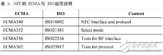
The NFC operating frequency is 13.56MHz, ASK modulation, and the transmission rate can be divided into three types: 106kbps/212kbps/424kbps. The communication mode can be divided into active mode and passive mode. The active mode refers to the initiating device (iniTIator) and the target device (target). RFfield can be generated by its own power supply, while in passive mode, the device itself supplies power to generate RFfield; while the target device uses full-wave rectification lines to convert the RFfield energy of the initiator to DC to supply its own power. It is worth mentioning that in the passive mode, in order to meet the requirements of power saving, the load modulation (LoadmodulaTIon) method is adopted, and the modulation mode can achieve the effect of power saving.
In use, because the use of NFC usually encounters the use of spikes, it will avoid data link errors caused by different initiators or target terminals communicating at the same time, so NFC adopts a mechanism listenbeforetalk. This mechanism will let the originating device detect the external magnetic field strength to determine whether other devices are communicating before sending the inquiry signal. The implementation of this mechanism is called RF Collision Avoidance (RFCA), and its action behavior is Each time the initiator sends an inquiry signal, the external magnetic field is detected. When the magnetic field strength exceeds the threshold intensity (Hthreshold = 0.1875 A/m), the inquiry is stopped until the external intensity falls below the threshold value. If the threshold value is lower than the threshold, the inquiry command will be issued. The detection time is TIDT+nTRFW, and n is the probability sampling of 0~3: TRFW=512/fc(RFwaitingtime), TIDT》4096/fc(initialdelaytime). When the initiating device does not detect a magnetic field exceeding the threshold intensity in the TIDT+nTRFW, the unmodulated RF field of the TIRFG is transmitted first and then an interrogation signal is sent, wherein the TIRFG must be greater than 5 ms.

Here we will describe the NFC RF interface. First, we must first introduce the EMCA340 and EMCA356 standards. The EMCA340 describes the NFC-related protocols. Here we introduce the data seals for discussion. NFC data subcontracting is divided into two types, one is 106kpbs. One is 212/424 kbps.
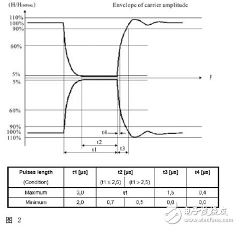
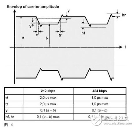
Since NFC106kbps is 100% ASK modulation, the packet structure of the entire High/Low signal is fairly well defined. Several of these parameters range from 100% down to 5% Am time (t1), 5% Am duration (t2), Am from 5% up to 60% time (t4), ie the range of overshoot. The 212/424 kbps is 8% to 30% modulation rate.
RF test kit:
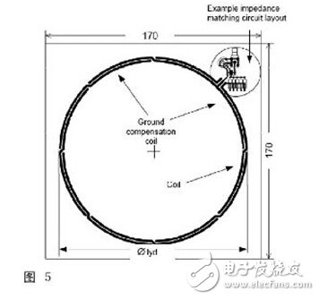
1.Calibration coil: The function of the coil is to verify whether the signal emitted by the object under test is the correct intensity and modulation during the test. This Coil is a simple antenna architecture. Of course, EMCA also specifies all the dimensions in detail, and the value measured by the coil is 0.32 V (RMS) = 1 A/m (magnetic field strength).
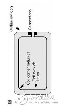
2. Field Generating Antenna: kit is used for the transmission of magnetic fields. The figure also contains a set of antenna matching lines.
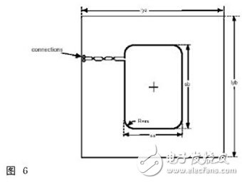
3.Sense coil: The sense coil is used to measure the magnetic field strength and modulation of the object to be tested.
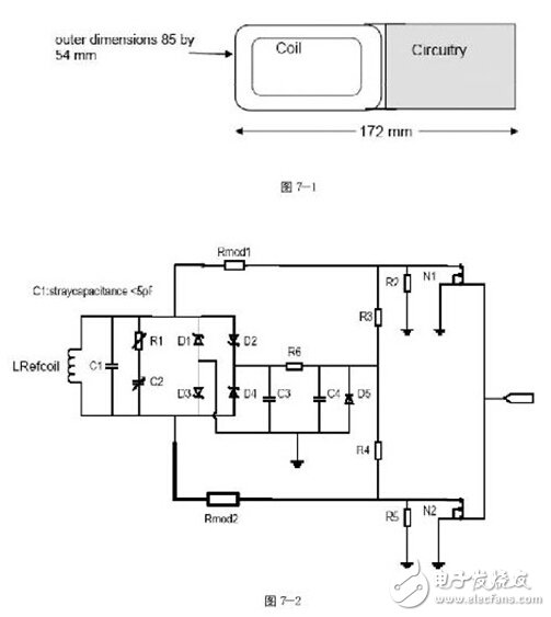
4. Reference device: Figure 7 shows two test standard lines and a set of antenna coils. This reference device is used to test the standard parts of the DUT. There are two sets of test circuits, Figure 7-2 shows the modulation test circuit, and Figure 7-3 shows the power test circuit.
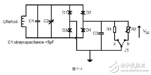
1. Initiating Device Power Test: This test tests whether the strength of the magnetic field supplied by the initiating device supplies enough working power to the target. The signal is adjusted by the generatingantenna, and the intensity measured by the calibrationcoil on the right side is Hmax (7.5A/m). At this time, the referencedevice is matched with the power test line to adjust C2 so that the line resonance point is at 19MHz (this part is in the specification and No detailed reason why it is adjusted to 19MHz, it is inferred that if 19MHz can reach 3V output, the voltage will be super high 3V when the target is 13.56MHz, which is the lower limit value), placed in the DUT position, adjusted The voltage value obtained by C3 by line R2 is 3V. At this point, the Referencedevice has been completed, and then the card is used to measure the initiating device, and the card is placed in the super-range range marked by the initiating device, and the voltage value measured at any position within the super-period range (C3) Do not exceed 3V. As for the Hmin test, it is roughly the same as max. The difference is that the referencedevice resonance frequency is adjusted to 13.56 MHz and the measured voltage value must exceed 3V.
2. Target's loadmodulation test:
(1) Passive mode
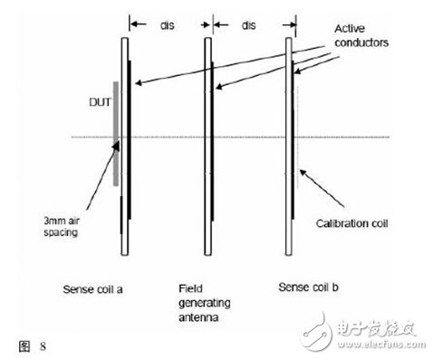
â— 106kbps: This test is to verify that the target can correctly change the waveform. First, place the calibrationcoil on the lower edge of the lower side to determine that the waveform and intensity emitted by the generatingantenna are correct. At this time, the object to be tested is placed on the upper side. Edge, edit a SENS_REQ waveform defined by ECMA340 by the generatingantenna and send back a SENS_RES signal to the target to be tested, so that the signal can be measured by two sensecoil measurements. The measurement architecture is based on the load of the backhaul. The variable signal is weak, so the voltage difference between the two sensecoil is used for calculation. Due to the compatibility problem, the MiFARE uses the subcarrier modulation as the return signal of the passive target at 106 kbps, so the measurement point should be Fc+fs and fc-fs (fc=13.56MHz, fs=fc/16).
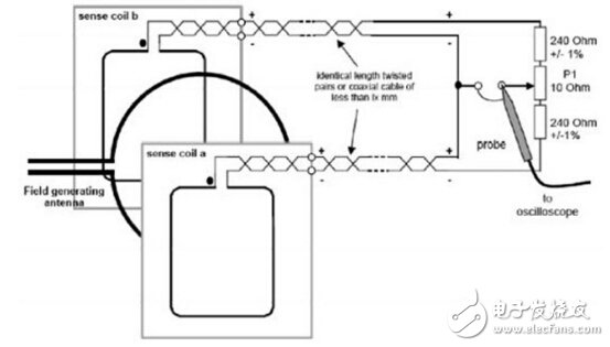
â— 212/424 kbps: The high-speed modulation signal measurement method is very similar to 106 kbps, except that the measurement acquisition position is changed to fc because subcarrier modulation is not used at these two transmission speeds.
(2) Active mode
The active mode test is not much different from the passive mode. Because it is the active mode, it adds the time of the RFfield of the target, the time of the command, etc.
3. Initiate the device's loadmodulation test:
This test consists in verifying the modulation mechanism of the initiating device, which can be divided into active mode transmission and passive mode reception.
(1) Active mode transmission: The calibrationcoil is placed at any position defined by the initiating device, and the measured waveforms are to comply with the specifications set by ECMA340.
(2) Passive mode reception: This is the signal that the test initiator can correctly receive the passive target. Using the referencedevice made by the loadmodulation test line in Figure 7-2, the relationship between the corresponding C3 voltage and the distance is first corrected by the architecture of Figure 8. After that, the card and the test object of the initiating device can be measured and tested. The modulation signal sent by the reference device is received at the object to be tested. Only some of the test items can be discussed here. For detailed tests, please refer to ECMA.
NFC system - there is a problem1. Compatibility issues
At present, the compatibility issues of NFC equipment from different manufacturers are still outstanding, which is also a focus of the NFC Forum is currently working on. It hopes to achieve the unification of compatibility of all NFC devices through NFC mark certification.
2, security issues
Secure NFC combines the security of smart cards with a variety of NFC applications. Important confidential data and data are stored in an area of ​​the secure memory of the card and can only be authorized by the NFC device to encrypt the transmitted data by a private key stored in the secure memory of the device.
3. Active or passive mode of operation
Devices with NFC can operate in active or passive mode. The general mobile devices operate in passive mode, which can greatly reduce power consumption and extend battery life. Active NFC devices provide all the power needed to communicate with passive devices via an internally generated RF-field, as in the case of contactless smart cards, with the same power, ensuring that even mobile devices are turned off The power supply can still read the data normally.
4. Standardization
NFC complies with the open platform technologies of ECMA 340 and ETSI TS 102 190 V1.1.1 and ISO/IEC 18092 standards, which specify the modulation scheme, coding, transmission speed and frame format of the RF interface of the NFC device, and passive Initialization settings and conditions required for data collision control during active NFC mode initialization. In addition, these standards also define transport protocols, including protocol initiation and data exchange methods.
5. Policy issues
Due to the complexity of the mobile payment industry, the construction of the value chain requires multiple participation. During this period, the industry leaders are not clear, the bargaining power of financial institutions and mobile operators is equivalent, and the actual investment in the industry is relatively low. Due to the lack of terminal and consumer environment, the user experience is poor, and the goods and services purchased by users through mobile payment are not abundant, and currently there is no real convenience for consumers.
NFC System - Common Certification RequirementsCurrently, the main certifications for NFC terminals are CE, FCC and NFC logo certification. The NFC logo certification is still a voluntary certification. In fact, the main test requirements in the phase are the interconnection and interworking (IOT) requirements of NFC equipment. The CE standards for NFC equipment are ETSI EN 300 330-1 and ETSI EN 300 330-2. The FCC certification standard for NFC equipment is FCC PART 15C. Specific test requirements can be found in the Moore Lab (MORLAB) feature article: "RF and FCC certification for RF testing requirements for the NFC band"
Wind Power Tower,Steel Wind Power Tower,Custom Wind Power Tower,Concrete Wind Power Tower
CRRC SHANDONG CO., LTD. , https://www.crrcsd.com