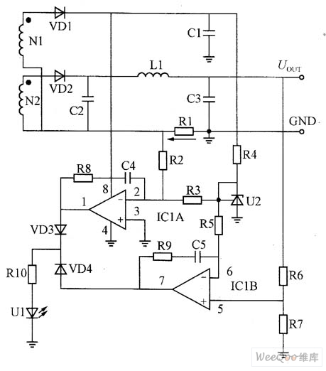
The figure is a constant voltage, constant current control circuit composed of LM358 amplifier and precision voltage regulator TL431.
The transformer winding N2 induced voltage is rectified by VD2, and the π filter circuit composed of C2, L1, and C3 obtains the DC output voltage on C3. The purpose of setting the N1 winding is to work normally when the output is shorted to ensure the safety of the circuit.
Constant voltage circuit working principle: U2, ICIB, R6, R7, VD4, R10, U1 form a voltage control loop. U2 (TL431) is a precision voltage regulator. The cathode K and the control electrode R are directly short-circuited to form a precise 2.5V reference voltage. R4 is the current limiting resistor of U2. The 2.5V reference voltage is sent from the resistor R5 to the ICIB inverting input (6-pin); the non-inverting input (5-pin) is set by the voltage divider ratio of R6 and R7. If the output voltage rises, the UR7 voltage also rises. This voltage is compared with the 2.5V reference voltage at the inverting terminal. The 7-pin output error signal is converted into a current signal through VD4 and RIO, and flows into the LED in the optocoupler, which is then controlled by feedback. The network controls the primary side PWM output duty cycle to operate the output voltage in a constant voltage state.
Constant current circuit working principle: U2, IC1A, R1, R2, VD3, R10, U1 form a current control loop. R1 is the output current sampling resistor, and the output current produces a voltage of R1/IOUT on R1.
drop. The voltage is directly sent to the non-inverting input terminal of the ICA (3 feet), and the 2.5V reference voltage is composed of a voltage dividing circuit composed of R2 and R3, and then the divided voltage is sent to the inverting input terminal (2 feet), and the output is output.
The voltage drop on R1 is compared with the 2.5V reference voltage divider voltage. The 1 pin outputs the error signal, and then becomes the current signal through VD3 and RIO, changing the current in the optocoupler LED, and then controlling the primary side through the feedback control network. The PWM output duty cycle makes the output characteristics show constant current characteristics. R8, C4, R9, and C5 are phase compensation components of IC1A and ICIB, respectively.
A constant voltage and constant current control circuit composed of an amplifier can achieve high constant voltage and constant current accuracy. Since the picture circuit uses an amplifier form, the resistance value of R1 can be selected to be mΩ level, which has no effect on circuit conversion efficiency.

The picture is composed of LM358 amplifier and precision voltage regulator TL341 constant voltage, constant current control circuit
Suizhou simi intelligent technology development co., LTD , https://www.msmvape.com