Increased clock speeds and tighter signal timing increase the need for precision high frequency modules. The PLL (Phase Locked Loop) generates a high frequency output signal based on the input signal and is a popular circuit for generating high frequency signals. When the PLL reference clock and the frequency and phase of the PLL feedback clock match, the PLL is said to be locked. The time required to reach the locked state is called the lock time, which is one of the most critical parameters of the PLL design. Therefore, it is necessary to measure very accurately.
Figure 1 shows a simplified block diagram of the PLL and its components.

In the phase-locked loop of Figure 1, the VCO signal is divided and sent back for comparison with the reference signal.
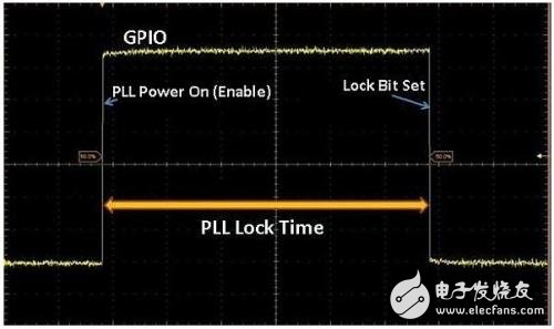
The PLL lock time is the time at which the PLL needs to match the target (between the PLL reference clock and the PLL feedback clock) to generate the target frequency after power-up. Figure 2 shows that the lock signal is high when the frequency of the feedback clock and the reference clock are the same.

Figure 2: When the frequency of the feedback clock and the reference clock are the same, the PLL lock signal is high.
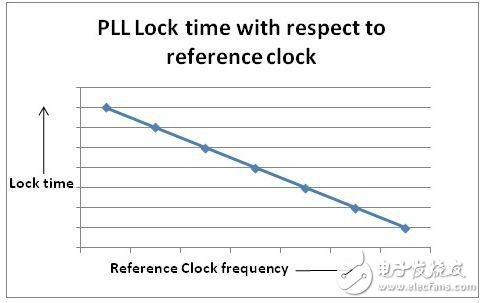
The design of the PLL is usually done in a way that keeps the locking time as short as possible while still providing the highest possible stability. Depending on the range of the reference frequency, the time taken to implement the locked state varies, as shown in Figure 3.

The lock time behavior of Figure 3 is linearly proportional to the reference frequency.
You can use any of the following methods based on available resources.
Method 1: PLL Power On, Lock Bit Assertion/DeassertionWhen the PLL power is turned on, the GPIO (General Purpose Input Output) pin is inverted. Then, the lock bit polls to check if the lock status has been achieved. When the lock bit is asserted/deasserted, the same GPIO pin is triggered again, as shown in Figure 4. The pulse width of the GPIO is the PLL lock time. This method can be used if the PLL clock output cannot be accessed.

Figure 4 PLL power on to lock bit assertion / deassertion
Unfortunately, this method is not very accurate, because there is a design margin for a certain lock time after the lock position is set.
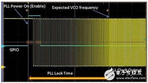
Method 2: PLL Power On to Expected VCO Clock OutputThis method works if the clock output pad of the PLL VCO (Voltage Controlled Oscillator) does not have a lock gate (regardless of the state of the PLL lock bit, the clock output pad drives the VCO clock). Since the VCO clock output pad has no lock gating, we can directly observe the VCO output. In this method, we measure the time interval between the PLL power-on time and the time to obtain the desired VCO output frequency, as shown in Figure 5. This time is the lock time.
The PLL frequency output required by the oscilloscope can be measured by manually placing the cursor for each cycle until a constant frequency is observed.

The utility model provides a disposable electronic cigarette, comprising: a hollow shell, the bottom of the shell is provided with a lower cover; the shell contains an atomizer, and the outer side of the atomizer is sheathed with a disposable cigarette A bomb, a microphone cover is arranged under the atomizer, a microphone is covered under the microphone cover, a battery is arranged on one side of the atomizer, and an upper cover is arranged on the top of the casing; The atomizer includes an atomizing core, an oil-absorbing cotton sleeved on the outside of the atomizing core, and an atomizer outer tube sleeved on the outside of the oil-absorbing cotton. The disposable electronic cigarette provided by the utility model absorbs the smoke oil on the surface through the absorbing cotton, and then atomizes the smoke through the atomizing core, which greatly reduces the risk of oil leakage, at the same time, reduces the burning of cotton and ensures the smoking taste.The utility model provides a disposable electronic cigarette, comprising: a hollow shell, the bottom of the shell is provided with a lower cover; the shell contains an atomizer, and the outer side of the atomizer is sheathed with a disposable cigarette A bomb, a microphone cover is arranged under the atomizer, a microphone is covered under the microphone cover, a battery is arranged on one side of the atomizer, and an upper cover is arranged on the top of the casing; The atomizer includes an atomizing core, an oil-absorbing cotton sleeved on the outside of the atomizing core, and an atomizer outer tube sleeved on the outside of the oil-absorbing cotton. The disposable electronic cigarette provided by the utility model absorbs the smoke oil on the surface through the absorbing cotton, and then atomizes the smoke through the atomizing core, which greatly reduces the risk of oil leakage, at the same time, reduces the burning of cotton and ensures the smoking taste.The utility model provides a disposable electronic cigarette, comprising: a hollow shell, the bottom of the shell is provided with a lower cover; the shell contains an atomizer, and the outer side of the atomizer is sheathed with a disposable cigarette A bomb, a microphone cover is arranged under the atomizer, a microphone is covered under the microphone cover, a battery is arranged on one side of the atomizer, and an upper cover is arranged on the top of the casing; The atomizer includes an atomizing core, an oil-absorbing cotton sleeved on the outside of the atomizing core, and an atomizer outer tube sleeved on the outside of the oil-absorbing cotton. The disposable electronic cigarette provided by the utility model absorbs the smoke oil on the surface through the absorbing cotton, and then atomizes the smoke through the atomizing core, which greatly reduces the risk of oil leakage, at the same time, reduces the burning of cotton and ensures the smoking taste.
maskking vape,maskking vape price,maskking vape review,maskking vape shop,,maskking vape cost,maskking vape disposable,maskking vape informacion
Suizhou simi intelligent technology development co., LTD , https://www.msmsmart.com