Generally, the implementation of a video processing system needs to support various video and audio standards and is responsible for converting signals from one standard to another. Multimedia applications require signals to be processed at the video rate, which means that the simulation must run in real time during development.
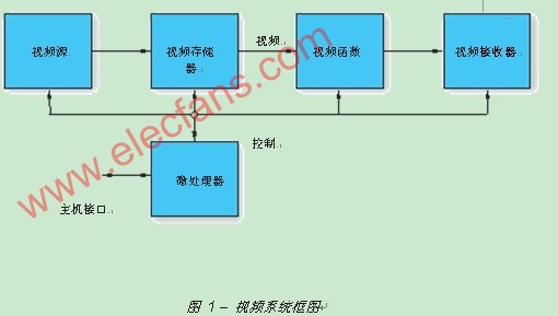
A typical video processing system uses a microprocessor to control a video pipeline, which includes a video source and sink, a large memory for storing video data, and a video processing system (Figure 1).
When implementing and debugging various video algorithms, you need to verify their functionality through software and hardware simulation. The real-time nature of the video stream and the large amount of video data required per frame make the simulation of video processing applications particularly challenging.
Design environment
The Video Basic Suite (VSK) supports the rapid development and debugging of high-performance video processing systems for a wide range of video applications. VSK uses Xilinx® Virtex-4 XC4VSX35 device, which is optimized for DSP processing through a high proportion of multiply-accumulate blocks (also known as DSP48) in the structure, and has a rich set of video interface features such as DVI, VGA , Component (HD), composite, S-video, SDI, etc.
Generally, the development of video algorithms requires the use of hardware to verify the video operations of real-time data streams, and the simulation environment is required to develop and test video processing components. VSK provides software simulation and real-time operation for each component of the video system, allowing you to develop video IP (including filters, video block sets, accelerators, and video interface conversion) or final applications such as codecs and image enhancements , Dynamic gamma correction and motion estimation. Integration with the tool suite and I / O diversity enable quick and easy introduction of video to the board and optimization of its running algorithms.
Also provided with VSK are reference designs, some of which are written in HDL and others are built using the Xilinx System Generator for DSP design environment. In order to remove the complexity of introducing data through various video interfaces and sending them to Virtex-4 devices, we have attached a video interface block set library so that all interface block sets can be controlled by a MicroBlaze controller.
In order to highlight some of the capabilities of VSK, I will explain the MPEG-4 Part 2 decoder demo design.

MPEG-4 Part 2
The MPEG-4 decoder demonstration system consists of an FPGA hardware evaluation platform, Xilinx IP core and embedded software, and together performs decompression operations on industry-standard encoded video bitstreams.
For this design, the FPGA is programmed to perform decompression and drive video display. A Compact Flash card is used to save multiple compressed video streams and FPGA configuration bit streams. An embedded processor inside the FPGA reads the bit stream from the Compact Flash card, writes it to an external DDR memory, and sends it to the MPEG-4 Part 2 decoder. Then, through the video I / O daughter card, reformat the output of the decoder to the video standard to be displayed on the external monitor.
The system overview is shown in Figure 2. MPEG-4 decoder core, DDR memory controller, color space converter, VGA interface, macroblock format converter, and MicroBlaze soft core processor and related peripheral circuits are implemented in XC4VSX35 FPGA. The ZBT memory, DDR memory, System ACE technology, Compact Flash connector, two-wire LCD display, and a digital-to-analog converter are all located on the hardware platform.

Embedded processor
Video systems generally require a control processor. The processor is usually used to communicate with the host system, establish video processing operations, calculate coefficients, and generally operate as a low-rate data processor. VSK has video standards for input and output sources, and cooperates with System Generator hardware co-simulation capabilities, allowing you to quickly test and debug the system through real-time video streaming.
In this MPEG-4 demo design, the embedded MicroBlaze processor is used as the overall system-level controller, handling the following functions, such as the user interface, reading the compressed bit stream from the Compact Flash card, and sending the bit stream to the MPEG-4 decoder Nuclear, and monitor all system status signs, etc.
The Xilinx System Generator for DSP greatly simplifies the design process of integrating MicroBlaze processors into the framework. You can use Xilinx System Generator with the Embedded Development Kit (EDK) software tool to implement and simulate a system with a processor and FPGA video processor function that operates on live video streams. System Generator automatically generates software drivers to support reading and writing data to the System Generator design. Both methodologies currently support the integration of a MicroBlaze controller:
The System Generator design is exported to the EDK system. When used in pcore (processor core) export mode, the memory mapped block and all other blocks are encapsulated into a pcore peripheral. Software drivers and documentation for the memory mapped interface are also generated and provided with the peripheral.
The EDK project is imported into the System Generator design for hardware co-simulation. When used in EDK import mode, import an EDK file into the System Generator by running the EDK import wizard. When the import wizard is complete, the EDK system is pulled into the System Generator design like a black box. During the import process, the EDK system is expanded through the Fast Simplex Link (FSL) interface, which is used to communicate with the memory map.
Hardware co-simulation
Watching the final output video is an important quality measurement indicator for all video systems. VSK's input and output source video standards, combined with System Generator hardware co-simulation capabilities, allow you to quickly test and debug your system through real-time video streaming.
The System Generator provides a hardware co-simulation interface. You can compile the System Generator diagram into an FPGA bitstream and associate the bitstream with a new runtime hardware co-simulation block. When the design is simulated in Simulink, the results of the compilation part will be calculated by hardware rather than software.
System Generator provides a high-speed hardware co-simulation interface that allows Simulink vector or matrix signals to be read from or written to FPGA hardware in a single transaction. By using these interfaces, you can greatly reduce the number of PC / hardware transactions in the simulation process, further speeding up the simulation speed, beyond the speed that traditional hardware co-simulation can achieve. Taking advantage of the popularity and advancement of Ethernet technology, this interface provides a convenient and high-bandwidth co-simulation method for external FPGA devices.
VSK supports two Ethernet co-simulation modes:
The network-based Ethernet hardware co-simulation interface provides co-simulation access to the FPGA platform through the IPv4 network infrastructure. Because IPv4 networks are widely distributed, this interface provides a way to communicate directly with remote hardware connected to a wired or wireless network. This interface is especially suitable for remote FPGA platforms (such as cross-bureau or cross-border), or where multiple designers must share a development board. The network-based Ethernet interface supports working in 10/100 Mbps half / full duplex mode.
Point-to-point Ethernet hardware co-simulation provides a co-simulation interface through the original Ethernet connection. The original Ethernet connection refers to the layer 2 (data link layer) Ethernet connection. It is located between a supported FPGA development board and a PC host. There are no routing network devices along the way. The point-to-point Ethernet interface supports working in 10/100/1000 Mbps half / full duplex mode. As long as the underlying connection supports it, it can also support the huge framework of Gigabit Ethernet connections.
VSK includes software, hardware, camera, cable and a detailed user guide and reference design. It includes a limited set of System Generator for DSP, ISE? Software, and embedded design kit (EDK) FPGA design tools, as well as a Xilinx ML402-SX35 development board, video I / O daughter card (VIODC), CMOS Image sensor camera, power supply and cable.
in conclusion
With this complete and easy-to-use solution, the video basic kit is an ideal hardware platform to evaluate Xilinx FPGAs into a wide range of video and imaging applications. By fully integrating and supporting Xilinx System Generator for DSP software, VSK can take full advantage of the new high-speed Ethernet hardware co-simulation capabilities to implement real-time system integration, development, and verification of codecs, IP, and video algorithms.
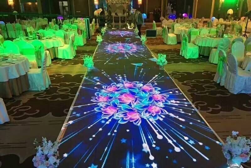
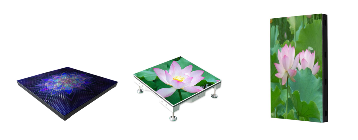
Dance Floor LED Display features: Dance Floor Led Screen features simple installation and strong applicability. It is suitable for indoor and outdoor use. The bearing capacity can reach 2 tons. The surface is made of PVC material. The surface is frosted. It has waterproof and antiskid functions. The bottom bracket is directly installed without other installation equipment. The base has screw design and the height can be adjusted.
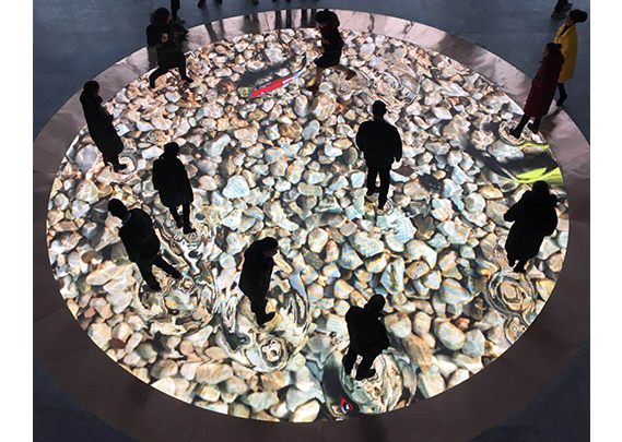
Dancing Floor Led screen effect: interactive Dance Floor Led screen reacts in millisecond when people interact with tile, and the perfect combination of real people and screen. interactive Dance Floor Led screen is divided into intelligent interactive tile screen and radar interactive tile screen. They have their own characteristics in use: intelligent interactive tile screen without external equipment, clean appearance, simple installation, random splicing, radar interactive tile screen with external interactive radar, applicable to glass mutual Moving plank road screen and outdoor bad weather make the interactive floor tile screen perfectly displayed in all application occasions.

Installation features and precautions: the floor tile screen is installed with a base and adjusting screws to effectively ensure the flatness of the screen body, leaving a certain gap at the bottom for drainage and heat dissipation. Before installing the floor tile screen, the floor should be reserved with a certain depth, which should be flush and beautiful with the floor after installation.
Application scenario: the cabinet size is mainly 500 * 1000mm and 500 * 500mm, mainly used in stage, concert, performance, bar, disco, shopping center and other fields.

Maintenance: front and rear maintenance, can directly replace a single box and a single module, without removing the adjacent box.
Display effect: highlight, good consistency, no time difference between interaction with people, people and stage display complement each other. Truly achieve the effect of integration of interaction.
Screen principle and structure: the screen has built-in intelligent interactive equipment with many contacts and sensitive sensing. The box body is directly connected with waterproof aviation plug, and the installation is quick.

Smd Screen,Dance Floor Led Display,Led Dancing Floor,Interactive Dance Floor Led Display
Shenzhen Vision Display Technology Co,.LTD , https://www.ledvdi.com