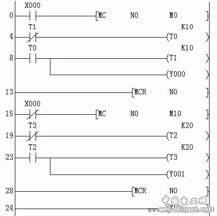
1. Application master control instruction to control programming of branch programs A and B
(1) Control requirements:
The A block is a flash output per second, and the B block is a flash output every 2 seconds. When the button X0 is required to be turned on, the A block is executed, the A lamp flashes once every second, and when the button X0 is turned off, the B block is executed, and the B lamp flashes every 2 seconds.
(2) Input/output signal definition:
Input: X0—Button output: Y0—A lamp Y1—B lamp
(3) The reference program (ladder diagram) is shown in the figure:

(4) Program analysis:
When X0 is turned on, the timers T0 and T1 work normally to form an oscillator, and the T0 contact waveform (output through Y0) is a square wave with a period of 2 seconds and a duty ratio of 50%; at this time, both T2 and T3 are reset. The Y1 output remains disconnected. When X0 is off, the timers T2 and T3 work normally to form the oscillator, and the T2 contact waveform (output through Y1) is a square wave with a period of 4 seconds and a duty cycle of 50%; at this time, T0 and T1 are reset. The Y0 output remains disconnected.
(5) Thinking:
Run the above program on the machine and observe: When the state of X0 changes, will the status of the output point in the program be saved?
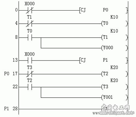
2, the application of the jump instruction to the branch program A and B control programming (modified on the basis of the main control instructions)
(1) Control requirements:
The A block is a flash output per second, and the B block is a flash output every 2 seconds. When the button X0 is required to be turned on, the A block is executed, the A lamp flashes once every second, and when the button X0 is turned off, the B block is executed, and the B lamp flashes every 2 seconds.
(2) Input/output signal definition:
Input: X0—Button output: Y0—A lamp Y1—B lamp
(3) Reference program (ladder diagram) as shown:

(4) Program analysis:
When X0 is turned on, the program jumps directly to END, and then executes from the beginning. The timers T0 and T1 are scanned. The waveform of Y0 is a square wave with a period of 2 seconds and a duty cycle of 50%. At this time, timers T2 and T3 Not scanned, keeping the previous state. When X0 is disconnected, the program jumps directly to statement number P0, timers T2 and T3 are scanned, and the waveform of Y1 is a square wave with a period of 4 seconds and a duty cycle of 50%; at this time, timers T0 and T1 are not scanned. , keep the previous state.
(5) Thinking:
1 Run the above program on the machine and observe: When the status of X0 changes, will the status of the output point in the program be saved? Compare the difference between a jump instruction and a master instruction.
2 Please explain the role of the label P1, put the label P1 at the beginning of the program, run on the machine, observe what will happen, and explain the reason.
3. Using the CJ command to realize the jog and self-locking control of the motor
(1) When the selector switch is set to the jog position and the start button is pressed, the motor runs immediately; when the start button is released, the motor stops immediately.
(2) When the selector switch is set to the automatic position and the start button is pressed, the motor runs immediately; when the start button is released, the motor is self-locking; when the stop button is pressed, the motor stops immediately.
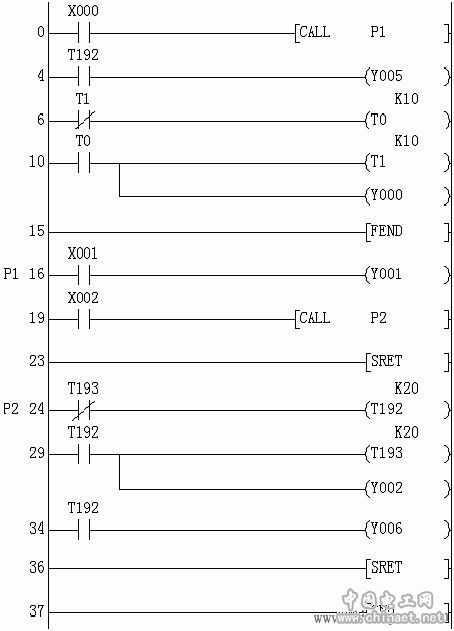
4. Application subroutine calls programming, pay attention to the change rule of various coil states after subroutine call
(1) Program running process:
1 Do not call the subroutine: X0=OFF, X1=OFF, X2=OFF, then Y0 flashes for one second, Y1=OFF, Y2=OFF, Y5=OFF, Y6=OFF.
2 Only call subroutine P1: first make X1=ON, X2=OFF, and jog X0=ON (first call subroutine P1), then Y0 still flashes for one second, Y1=ON; then make X1=OFF Then observe the state of Y1, Y1 is still ON; then X0=ON (the second subroutine P1 is called), then Y0 still flashes for one second, and Y1=OFF. (Note: The state of the coil will be latched after the subroutine is called and will not change until the next call).
3 Continuously call the subroutine P1→In the subroutine P1, call the subroutine P2 (subprogram underset): first make X2=ON, X1=OFF, then make X0=ON (continuously call subroutine P1 and subroutine P2) , the output Y0 still flashes for one second, and Y5, Y6 and Y2 flash for 2 seconds. The restrictions and usage rules, use T0, T1 instead of T192, T193 and then run the program to observe the running results.
5, application interrupt, loop, refresh warning timer command programming, and pay attention to the control effect of the timer on the output coil in the interrupt service subroutine (comparing the lighting out of Y1 and Y3)
(1) Program running process:
1 Execute only the loop program: X10=OFF, monitor M0, M1, M2 and D0, and note (D0)=+32767+1→(D0)=-32768; observe the relationship between Y0 light off and (D0) value.
2 The first interruption: first make X11=ON, and jog X3, then Y2 lights up first, and Y1 lights up, Y3 does not light. The state of Y3 must wait until another interrupt occurs to change.
3Second interruption: When X11=ON, jog X3 again, then Y2 and Y1 are on, then Y3 is on.
4X11 turns OFF from ON, and when it is interrupted again, Y2=OFF, Y1=OFF, Y3=OFF.
Note: Even if the set value of T192 is K=0, Y3 will not turn on during the first interrupt of X11=ON.
(2) The reference program (ladder) is as follows:

4 In the Mitsubishi FX series, change the “CALLP1†command to “CALL(P)P1†command, then make X2=ON, repeatedly jog X0=ON, observe the change of Y6 and Y2 states, and pay attention to timer T192 (or The relationship between the timing of T193) and X0=ON. Once T192 is started, even if X0=OFF, the timing will continue until the set value, but the contact is turned on to immediately control the ladder diagram outside the subroutine, and only when the ladder diagram in this subroutine is called again. Take control.
(2) Reference program (ladder diagram) as shown:
(3) Thinking: Run the above procedures on the machine to answer the following questions
1 The effect of adding P and not adding P to the running result in the program debugging process.
2 timers.
Online Expansion Of Lithium Ion Battery
25Ah Modules Battery,Bluetooth App Battery,Remote Monitoring Battery,Custom Lithium Battery
Wolong Electric Group Zhejiang Dengta Power Source Co.,Ltd , https://www.wldtbattery.com