In recent years, wireless sensor networks have developed rapidly and are widely used in the fields of environment, security, process control and health monitoring, improving the efficiency of resource utilization, realizing the intelligence of the natural environment and engineering control, and improving the security of the public domain. The level has profoundly affected all aspects of human society. However, a large number of wireless sensor nodes also bring some problems to be solved, especially the demand for energy. Moreover, in many applications, in order to reduce costs, wireless sensor nodes are designed as low-cost, low-maintenance devices, which poses greater challenges for sensor calibration, package design in harsh environments, and especially power supply. With the development of technology, although the battery technology performance has been greatly improved, it still can not keep up with the growth rate of wireless sensors for energy demand. For this reason, it is a current research hotspot to obtain energy from the external environment to power wireless sensors. The various new environmental energy sources being developed mainly include solar energy, thermal energy, vibration energy and radio frequency energy. As a kind of mechanical energy ubiquitous in the natural environment, vibration energy is less restricted by external conditions and easy to collect and utilize. It is an ideal alternative energy source for wireless sensor networks.
1. Principle of vibration energy collection
Vibration energy harvesters typically use piezoelectric materials to convert vibration energy to electrical energy. The vibration energy harvester is fixed on the vibration source by the structure of the cantilever beam. When the mechanical vibration is generated, the piezoelectric crystal is deformed, and a current is generated in the circuit. As the direction of the vibration changes, the direction of the current also changes. Therefore, a circuit model based on an ideal current source can be established, as shown in FIG. It contains a sinusoidal current source i(t), an internal capacitor Cp and an internal resistor Rp. Where i(t)=Ipsin(2Ï€ft), the size of Ip is determined by the amplitude, f is the vibration frequency, Cp and Rp are constants that are not related to the vibration frequency, and the resistance of Rp is always very large. Past studies have shown that the output voltage (current) of a piezoelectric material depends on the geometry of the material, piezoelectric properties, mechanical vibration strength, and output impedance [2].
2. Optimization analysis of vibration energy collection
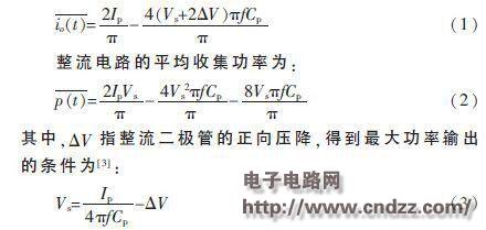
Since the vibration energy harvester outputs an alternating current (current) signal, it is first converted to a direct current voltage using a rectifier circuit, as shown in FIG. Where Cs is a storage capacitor for accumulating the collected power, i0(t) is the output current value of the rectifier circuit, and Vs is the output voltage value of the rectifier circuit.
According to the circuit analysis, the average output current of the rectifier circuit is:

At this time, Vs is called the optimal value of the rectified output voltage of the vibration energy collector, and the influencing factors include Ip, f and Cp. Ip is in turn dependent on the amplitude of the vibration, f is the vibration frequency, and Cp is determined by the characteristics of the piezoelectric material and can be considered as a constant. It can be derived from this that the AC voltage (current) signal output by the vibration energy harvester has an optimum value and is determined by the vibration amplitude, frequency and piezoelectric material characteristics. Therefore, manufacturers of vibration energy collectors generally give a plot of collector output power versus operating voltage and vibration amplitude at a particular vibration frequency. For example, the VOLTURE series vibration energy harvester V25W produced by MIDE is used to maximize the output power when the vibration frequency is 40 Hz and the vibration amplitude is 0.25 g, 0.375 g, 0.5 g and 1.0 g, respectively. The equivalent open circuit voltages are 4 V, 7 V, 8 V, and 15 V, respectively.
3, vibration energy collection power supply design
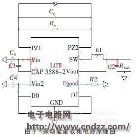
After the collected electric energy is converted into DC, it needs to pass through the voltage regulator circuit for the load to be used. In the traditional method, the rectifier circuit and the voltage regulator circuit are composed of discrete devices such as a rectifier diode, a storage capacitor, a protection diode and a three-terminal regulator. The circuit debugging is difficult and the conversion efficiency is low [4]. Linear Technology recently produced a power chip LTC3588-2 dedicated to vibration energy harvesting. It integrates a rectifier bridge, voltage regulator and control circuit. The power circuit formed by it is very simple, as shown in Figure 3. Among them, PZ1 and PZ2 pins are connected to the vibration energy harvester, and D0 and D1 pins are used to select the output voltage value (3.45 V, 4.1 V, 4.5 V, 5.0 V optional). This circuit is selected as 5.0 V output, Pgood The foot acts as a warning signal that the regulated power supply is “readyâ€.

Among the components used in the circuit, the key is the choice of the input storage capacitor Cs. In the vibration energy harvesting circuit, the most important characteristic of the storage capacitor is the low leakage current, and the equivalent series resistance value is not important. Considering the influence of leakage current, charging capability and electrical parameter stability on the circuit, TRJ series tantalum capacitor It is the best choice for vibration energy collection [5], so Cs selects a TRJ tantalum capacitor with a capacity of 22 μF and a voltage of 25 V.
4. Test and conclusion
Using a vibrating table as a vibration source to simulate environmental vibration, MIDE's V25W vibration energy harvester with a vibration frequency of 40 Hz and a vibration amplitude of 1.0 g was used to fix the vibration beam on the vibrating table with a cantilever beam structure, and a weight of about 16 g was attached to the end. Used to adjust the collector's own frequency to 40 Hz to match the vibration source frequency.
After the vibration table starts to vibrate, the AC voltage output from the vibration energy harvester is very smooth, conforming to the characteristics of the sinusoidal signal. Its peak-to-peak value is about 13 V, very close to the open circuit voltage at the maximum output power, the signal period is 25 ms, the frequency and the vibration source frequency. Consistent.
LTC3588-2 converts the AC voltage into DC voltage and charges the input storage capacitor Cs. The voltage Vs across Cs slowly climbs. Once the rising edge threshold voltage (16 V) is crossed, the chip turns on its internal voltage regulator circuit and puts the Cs on The charge is transferred to the output storage capacitor C2, and the output voltage VO instantly climbs to 5 V to supply power to the load. At the same time, the "ready" signal Pgood is set high, indicating that the regulated power supply can be used. When Vs drops to the falling edge threshold voltage due to the charge transfer, the chip turns off its internal voltage regulator circuit and stops the charge on Cs, so that the voltage across Cs rises again.
Test results show that the vibration energy harvester is properly installed and connected to the developed power circuit board, which can generate intermittent 5 V stable voltage, which can be widely used in wireless sensor devices with low power consumption and short working time.
Smart Watch,Smart Watch Women,Sport Smart Watch,Heart Rate Smart Watch
GANSU PINGLINAG ABAY SCIENCE&TECHNOLOGY CO.,LTD , https://www.yzwtech.com