TOP1 dangerous goods processing robot control circuit design
This paper first briefly introduces the role of dangerous goods handling robots, the structural form of the manipulator, and focuses on the design and implementation of the control system for dangerous goods handling robots from the control system and hardware design. Finally, the technical indicators of the measured robot are given. Dangerous Goods Handling Robots are devices that can be carried and placed for the handling, removal, handling and placement of dangerous ammunition. The completion of the project will solve the problem of safe handling of dangerous ammunition such as accident shells and war remnants that have long plagued our army. The manipulator is an important component that directly contacts the ammunition during the operation of the dangerous goods handling robot. It is mainly used to carry out the clamping, dismantling, handling and placing of dangerous ammunition. The stability of the manipulator work directly determines the success rate of the ammunition treatment. The design of the robot is crucial.
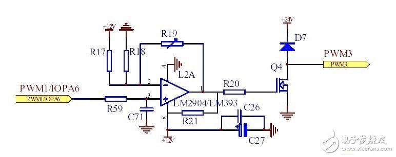
PWM pin: Each event manager of the DSP has a PWM circuit associated with the compare unit, which can generate six PWM outputs with programmable dead band and output polarity, but all are in pairs, which is required for this controller. Independent output, each event manager has only 3 channels, one DSP has two event managers, which can output 6 PWM waves independently. The hydraulic controller requires 6 PWM waves to drive the electric proportional valve, and the servo motor controller needs 4 0-5V accelerator signals to adjust the motor speed. When designing the circuit, the two circuits are designed together and made into a printed circuit. Plate, soldering board can be welded according to the function of each board. The hydraulic controller needs to output PWM waveform. The chip uses LM393 as comparator. At this time, resistor R19 and capacitor C71 are not soldered, but R21 pull-up resistor, R17 And R18 is suitable for dividing the voltage of 2 feet to about 1.7V. The servo controller needs to output 0-5V voltage chip for LM2904 for operation. The welding resistor R19 and capacitor C17 do not need MOS tube, R21 and external power supply, and do not need to solder R17, directly amplify the DSP output 0-3.3V voltage to 0- 5V output. The PWM/voltage output circuit diagram is shown in Figure 1:

Figure 1 PWM / voltage output circuit
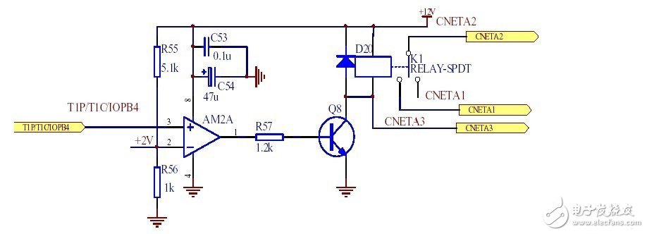
I\O port: DSP's digital I/O port module has the function of controlling dedicated I/O and multiplexed pins. It can output input high and low level signals, design it into switching output according to its function, input, and use it. Control the relay as a controlled switch. The digital input can be divided by a resistor, and the digital output is isolated by optocoupler. The optocoupler PC817 used in this design is more suitable for DSP. When the DSP outputs a high level, the relay is closed. The circuit diagrams of the CNETA1 and CNETA2 two-way conduction relays are shown in Figure 2:

Figure 2 relay circuit diagram
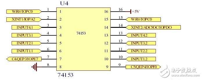
QEP Circuitry: Each time manager of the DSP has a Quadrature Encoder Pulse (QEP) circuit. The quadrature encoded input pulses on the CAP1/QEP1 and CAP2/QEP2 (for EVA modules) pins can be decoded and counted when the QEP circuit is enabled. An orthogonal coded pulse circuit can be used to connect the photoelectric encoder to obtain the position and velocity of the rotating machine. The servo motor controller needs to use the QEP circuit. Since one servo motor controller needs to control 4 servo motors, the code wheel signal uses 74153 chip to select input, and each signal of the code wheel has positive and negative lines through the op amp. After inputting the DSP to 74153, the code disc selection circuit is shown in Figure 3:

Figure 3 code disc selection circuit
Where W/R/IOPC0 is the enable signal, XINT1/IOPA2 and XINT2/ADCSOC/IOPDO form the select signal, and 74153 selects a pair of signals from the 7-pin and 9-pin outputs to the DSP by selecting the signal selection code. Other hardware circuit designs, including power supplies, serial ports, CAN buses, and DSP peripheral wiring, are typical designs. The design of the whole robot car has been installed and debugged. The manipulator fully meets the design requirements and achieves the following technical indicators: the maximum working range is about 2.5m; the maximum working depth is 1m underground; the clamping lifting force is ≤80kg under the maximum working amplitude; the maximum clamping ammunition diameter is 160mm. At present, there is no such professional mass production of dangerous robots in China. The successful completion of this product has laid a solid foundation for future mass production, and the market potential is huge.
Circuit design of relay race robot system
The mechanical part of the relay robot adopts the remote control car, which is stylish in style and gorgeous in color. The torch assembled on the car has the "2008 Olympics" logo, and the internal colorful electronic flame dances and flickers, which is pleasing to the eye. At the beginning of the game, the first robot car was manually started, and the torch on the car was lit at the same time. When the next robot car was encountered, the next robot car torch automatically lights up and starts to advance. In order to render the effect, at the end, the Arc de Triomphe composed of bright flowers is also designed. When the robot car wins to the end of the Arc de Triomphe, the circuit automatically triggers the fireworks, accompanied by sound and light, and has a strong visual impact.
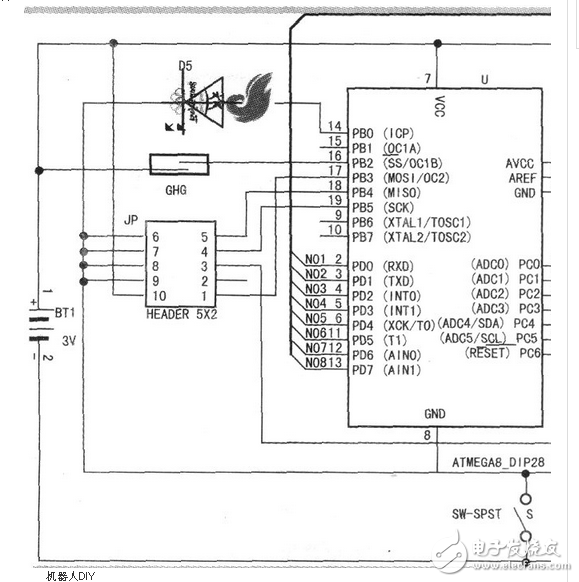
Circuit principle: a motor drive circuit L293D, an infrared photoelectric switch TCRT5000 and a resistor R2 four things constitute the most simple robot with tracking function. The TCRT5000 consists of a pair of phase-separated infrared transmitting and receiving diodes. The TCRT5000 is mounted face down on the chassis of the robot car. The emitting diode emits infrared light to the ground, and the receiving diode receives infrared light reflected from the ground. The robot uses the ATMAGE8 microcontroller. The internal integrated analog-to-digital conversion function, the ground reflection of different colors is different, so the intensity of the infrared signal received by the receiving diode is different, and the analog-to-digital conversion is performed by the ATMAGE8 single-chip microcomputer.

Different infrared signal strengths are converted to different values. According to this, the ground stitch can be recognized, and the program automatically controls the wheel motion through the motor drive circuit L293D to realize automatic tracking. The reed switch GHG is used to realize the relay. Each car is equipped with a magnet at the front end and a reed switch at the rear end. When the rear car is close to the front car, the magnet at the front end of the rear car acts on the reed switch at the rear end of the front car. Relay signal. The infrared emitting diode D3 and the infrared receiving diode D4 are used to cooperate with the robot to realize the parking function after the relay is completed. An infrared receiving diode D4 is installed at the front end of each vehicle, and an infrared emitting diode D3 is mounted at the rear end. When the magnet acts on the reed switch and transmits the relay signal, the front vehicle emits infrared rays through the infrared emitting diode D3 at the rear end, and the rear vehicle stops moving forward after receiving the infrared rays through the infrared receiving diode D4 at the front end.
For more information on robotics, circuit diagrams and DIY designs, see the Designs of week.
Vc Enzyme Combo Repair Shampoo
Orange has a fragrant shampoo having stable paste consistency suitable, white color, lasting aroma characteristics, have a good effect hair care and hair fixed.
Companies registered capital of 35 million yuan, the end of 2014 the total assets of 48.69 million yuan, including fixed assets of 37.52 million yuan. The company's existing cooperation Orange cultivation base 7043.5 acres, the company production base is located in Jiangxi County Tech Industrial Park Chu Tan industrial area, covers an area of 120 acres, it has built a standard plant 9,000 square meters, Nissan 6000 kg Orange enzymes and other liquid enzyme products. Enzyme, known as enzyme, refers to a polymer substance having biocatalytic functionality. In the catalytic reaction system an enzyme, the reactant molecules are known as substrates, enzyme substrates by catalytic conversion to another molecule. Almost all cellular activity of enzymes involved in the process are required to improve efficiency. Similar to other non-biological catalysts, enzymes chemical reactions by lowering the activation energy to accelerate the rate of the reaction, most of the enzyme catalyzed reaction rate can be increased a million times; in fact, the enzyme is to provide an activation energy needs than another low way, so that more particles to have less than the activation energy of the reaction kinetic energy, thus speeding up the reaction rate. Enzyme as a catalyst, in itself is not consumed during the reaction, it does not affect the chemical equilibrium reactions. Positive enzyme catalysis, but also a negative catalytic effect, not only to accelerate the reaction rate, but also to reduce the reaction rate. And other non-living catalysts is different, having a high degree of specificity of enzyme, only a catalytic reaction or produce a particular specific configuration.
Vc Enzyme Combo Repair Shampoo,Orange Aromatic Flavor Enzyme Shampoo,Hair Repair Enzymes Shampoo,Clean Hair Scalp Enzyme Shampoo
Ganzhou Green days Biochemical Technology Co., Ltd. , https://www.cn-gangdao.com