The adjustment tube is the output power tube in the regulated power supply. It is equivalent to an adjustable resistor in the regulated power supply circuit. With the fluctuation of the input voltage, the conduction degree of the tube is adjusted at any time after sampling by the sampling tube to achieve the purpose of stable output voltage. The degree of conduction of the rectifier is different.
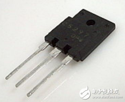
The voltage between the adjustment tubes CE is also different. When the input voltage is high, the voltage between the adjustment tubes CE is high. When the input voltage is low, the voltage between the adjustment tubes CE is low. The voltage higher than the regulated output is all added to the adjustment tube. The power loss of the adjustment tube is large, so the adjustment tube has a heat sink. The picture below shows a three-legged adjustment tube.
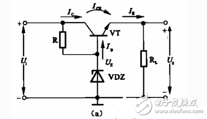
The so-called series regulator circuit is a series of triodes between the input DC voltage and the load. Its function is to change the UcP of the triode through some feedback form when the q or RL changes and the output voltage Uo changes. To adjust the output voltage to play, to keep the output voltage substantially stable. Since the stringed triode is used for adjustment, it is called an adjustment tube.
Figure (a) shows the basic regulator tube regulator circuit. In the figure, the transistor VI' is an adjustment tube. In order to analyze the voltage regulation principle, we have redrawn the circuit shown in Figure (a) into the form shown in Figure (b). At this point, we can clearly see that it is essentially based on the circuit shown in the figure. In addition to the emitter follower. According to the characteristics of the circuit, it is known that 乩 and Uz are follow-up relationships, so as long as the voltage Uz of the Zener tube is kept stable, 乩 can be substantially stabilized when 矾 and IL change within a certain range. The outstanding feature of the addition of the medulla is that the ability to carry the load is enhanced.
2, using power MOSFET adjustment tube to form an ultra low dropout linear regulator circuitIt is generally believed that the linear regulator has low conversion efficiency but low output ripple voltage, while the switching DC/DC converter has high conversion efficiency, but its output ripple voltage is high (1 to 2 higher than the linear regulator). Magnitude). If a power MOSFET is used as the adjustment tube, an ultra-low dropout linear regulator can be formed, which not only has a small output ripple voltage, but also has a conversion efficiency comparable to that of a DC/DC converter.
Portable electronic products hope to have a long battery life (or a long time interval between charges). The ultra-low voltage linear regulator described in this paper can meet this requirement and has better output accuracy.
Linear regulator circuit The author uses the Si9933 power MOSFET as the regulation tube to design a linear regulator circuit that is powered by the battery (input voltage 6V), output 5V, output current 500mA, as shown below. It is basically the same as the general linear regulator circuit. In order to improve the accuracy of the reference voltage, the TL431 precision adjustable reference voltage source is used here instead of the general Zener diode. This is because the general Zener diode has a low accuracy of 3V or less, and its dynamic resistance Rz=30Ω. In addition, a trimmer potentiometer RP is provided to adjust the RP to obtain the required initial voltage at no load (because the TL431's reference voltage is typically 2.495V. The minimum is 2.470V and the maximum is 2.520V).
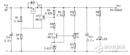
Its working principle is as follows: If the output voltage VOUT increases, that is, the output voltage ↑, VT3 base voltage ↑, VT3 IC3↑, R3 voltage drop ↑, VT2 VBEt, VT2 ic2↑, R2 voltage drop ↑, so that the pressure drop on R1 ↓, that is, the -VGS P of the P tube, the internal resistance of the P tube ↑. Make the VOUT output voltage ↓.
3. 2.5-24V regulated power supply with IGBT as the adjusting tubeThe power supply is basically used in this figure. The MOS tube is directly replaced with an IGBT, and the current-limiting sampling resistor slightly changes by about 0.3 Ω. Protected at around 2A (measured).
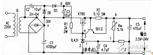
As shown in the figure, the 220v voltage is stepped down by transformer B, D1-D4 rectified, and C1 filtered. In addition, D5, D6, C2, C3 form a voltage doubler circuit (making Vdc=60V), Rw and R3 form a voltage dividing circuit, T1431 and R1 form a sampling and amplifying circuit, 9013 and R2 form a current limiting protection circuit, and the field effect transistor K790 is adjusted. Tubes (which can be used in parallel) and C5 are output filter circuits. The voltage regulation process is: when the output voltage is lowered, the potential at point f is lowered, and the voltage at point e is increased by internal amplification of T1431. After the adjustment of K790, the potential at point b is increased; conversely, when the output voltage is increased, the potential at point f is increased. The potential at point e decreases, and after adjustment by K790, the potential at point b decreases. Thereby the output voltage is stabilized. When the output current is greater than 6A, the transistor 9013 is turned off, so that the output current is limited to 6A, thereby achieving the purpose of current limiting. This circuit has 2W for resistor R1 and 5W for R2. There are no special requirements for other components. The component parameters are shown in Figure 3.
In addition, the k790 can be replaced by a K72515A500V125W tube. Because it is a voltage type device, there is no need to consider the driving problem.
4, using the composite tube as the adjustment tube of the power supply circuit diagramIn the regulated power supply, the load current Ifz flows through the regulating tube, and the power supply that outputs the large current must use a high-power adjusting tube. This requires a large enough current to supply the base of the adjusting tube, and the comparative amplifying circuit cannot be supplied. The large current required, on the other hand, the adjustment tube needs to have a higher current amplification factor in order to effectively improve the voltage regulation performance, but the high power tube generally has a low current amplification factor. The solution to these contradictions is to equip the original adjustment tube with one or more "assistants" to form a composite tube. The stabilized power supply circuit using the composite pipe as the adjusting tube is shown in Fig. 5-24.
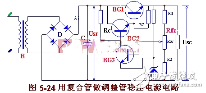
When the composite pipe is used as the adjusting pipe, the reverse current Iceo2 of BG2 will be amplified. Especially when the high power manifold is used, the reverse cutoff current Icbo is relatively large, and increases exponentially with increasing temperature, which is easy to cause high temperature no load. The out of control of the regulated power supply increases the output voltage Usc. The error signal ΔUsc is amplified to the level base of BG2 to reduce the Ic person, possibly forcing BG2 to turn off. In order to make the adjustment tube work in the amplification area at different temperatures, the base plus resistance (R7) of BG1 is often connected to the positive pole of the power supply (as shown in Figure 5-24) or the negative pole. This resistance may not be added when the temperature or load does not change much or when the silicon tube is used in its entirety.
Regulated power supply with protection circuit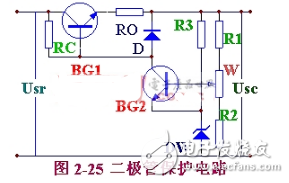
In the voltage regulator circuit, short circuit protection measures must be taken to ensure safe and reliable operation. Ordinary fuses are blown slowly, and the fuse is not used to protect them. A protective circuit must be installed.
The function of the protection circuit is to protect the tamping tube from being burnt when the circuit is short-circuited and the current is increased. The basic method is that when the output current exceeds a certain value, the adjustment tube is in a reverse bias state, thereby being turned off, and the circuit current is automatically cut off.
There are many forms of protection circuits. Figure 5-25 shows the diode protection circuit consisting of diode D and the sense resistor R0 of the 5-25 diode protection circuit. During normal operation, although the voltage across the diode is low, the diode is still in the reverse state. When the load current increases to a certain value, the depression ROIe on the resistor RO is increased to turn on the diode. Since UD=Ube1+ROIe and the on-voltage UD of the diode is constant, Ube1 is forced to decrease, so that Ie is limited to a certain value to achieve the purpose of protecting the adjustment tube. When using, the diode should use a large UD value.
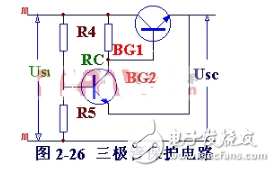
Figure 5-26 shows the triode protection circuit. It is composed of a transistor BG2 and voltage dividing resistors R4 and R5. When the circuit works normally, the base potential of BG2 is higher than the emitter potential through the pressure of R4 and R5, and the emitter junction is subjected to the reverse voltage. Therefore, BG2 is in the off state (equivalent to an open circuit) and has no effect on the voltage regulator circuit. When the circuit is short-circuited, the output voltage is zero, and the emitter of BG2 is equivalent to ground. Then, BG2 is in a saturated conduction state (corresponding to a short circuit), so that the base and emitter of the adjustment tube BG1 are nearly short-circuited, and are in an off state. Cut off the circuit current to achieve the technical specifications of the regulated power supply and the requirements for the regulated power supply.
Disposable Vape Pen,Disposable Vapor Pen,Disposable Vapes,Vape Disposable Pod
Shenzhen Xcool Vapor Technology Co.,Ltd , http://www.xcoolvapor.com