The uniqueness and stability of fingerprints make it one of the widely used biometric technologies. I love the scheme of smart home fingerprint recognition access control system introduced by F3, which uses FPI fingerprint identification module, combined with Linux design. Achieve accurate and fast authentication to achieve the function of opening and closing the door and the fast alarm function.

Before introducing the design, let's review the principles of fingerprint recognition.
First, the technical principle of fingerprint recognition
The technical principle of fingerprint recognition is to find out whether the fingerprint data matches the fingerprint collection from the fingerprint database, and achieve the purpose of switching the door lock by distinguishing the identity. The basic principle is shown in Figure 1. The fingerprint identification system consists of fingerprint image acquisition, fingerprint image preprocessing, fingerprint feature extraction, fingerprint feature matching, and feature database. Fingerprint image preprocessing uses Gabor filtering method to perform grayscale filtering to denoise. After filtering the image, it is binarized to filter out or correct various noises. The fingerprint feature extraction is based on the statistical analysis of the neighbors of the point 8. The feature points are obtained by calculating the CN (Croosing Number). The process of fingerprint feature matching is a process of calculating the similarity degree of two fingerprints. Before fingerprint matching, different fingerprint images must be calibrated to find the best transformation between the input feature point set and the template feature point set.
The fingerprint identification system can be roughly divided into two parts: fingerprint registration and fingerprint comparison. Fingerprint registration mainly includes fingerprint collection, fingerprint image preprocessing, feature point extraction and feature value storage. The first 3 steps of the fingerprint comparison are exactly the same as the fingerprint registration. After the feature points are extracted, the generated fingerprint feature values ​​will be matched with the feature values ​​stored in the fingerprint feature database, and the matching result will be output.

Figure 1 The basic principle of fingerprint recognition technology
Second, fingerprint recognition access control hardware principle
The fingerprint identification access control system designed in this paper is mainly composed of FPI fingerprint identification module, Raspberry Pi main control module and AVR module. The hardware structure is shown in Figure 2.
The three-party communication realizes the fingerprint input and matching of the user, and the switch of the door lock, and monitors the state of the door lock by sending an email.
·FPI fingerprint recognition module's powerful image processing function is very sensitive to fingerprint recognition, timely processing received fingerprint information, and communicating with Raspberry Pi;
Raspberry Pi module, on the one hand, controls the AVR to detect the switch status of the door and switch the door lock, on the other hand controls FPI fingerprint entry and matching, and establishes a database to record user information on the Raspberry Pi;
The controller AVR feeds back to the switch state of the Raspberry Pi door, and controls the motor to open and close the door lock, which enhances the hardware expansion and can monitor the door in more aspects through hardware.
In addition, the wireless communication module is used to avoid the damage of the original door lock structure caused by excessive wiring, and the hardware composition of the system is convenient and fast.

Figure 2 Hardware structure of the fingerprint identification system
Fingerprint identification module
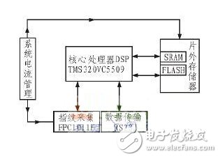
The fingerprint module is based on TI's TMS320VC5509 advanced digital DSP processor as the main core, and the chip structure block diagram is shown in Figure 3. High-precision optical acquisition head (TFS-D0307), high-speed, stable; standard UART interface communication, standard 8-byte communication protocol, FPI finish processing the received fingerprint information, and communicate with the Raspberry Pi main control module.

Figure 3 fingerprint identification chip FPI
Image acquisition chip
The image acquisition chip FPC1011F is integrated on the FPI chip. The FPC1011F fingerprint sensor is a capacitive semiconductor sensor device. The capacitive fingerprint sensor utilizes a reflective detection technology and belongs to a planar acquisition fingerprint sensor. Compared with the traditional capacitive sensor, it collects the dermis layer of the finger and has good applicability to wet and dry fingers. FPC1011F fingerprint acquisition principle: FPC1011F fingerprint sensor is composed of 152 & TImes; 200 sensor arrays, each array is a metal electrode, acting as a pole of the capacitor, the corresponding point of the finger on the sensing surface is another The pole is operated by a capacitive sensor based on the pitch of the pole plates. The capacitance is determined by equation (1):

(where: C is the capacitance; d is the plate spacing; ε0 is the vacuum dielectric constant; εr is the relative dielectric constant of the interplate plate; s is the effective area of ​​the plate)
When the finger touches the conductive frame of the sensor, it can be known from equation (1) that the valley and the ridge have different capacitance values ​​C due to the different distance from the sensor array, and the operational amplifier circuit forms different voltage values ​​through the internal A/. D conversion to obtain high quality digital fingerprint images.
processor
The main processor used in this system is the 32-bit fixed-point high-speed digital DSP processor of TMS320VC5509. The hardware of the development board includes: USB2.0 FullSpeed ​​interface for transmitting high-speed data such as images and video; 1M BytesFLASH for off-chip expansion; RTL8019AS network interface The chip realizes the Ethernet communication Ethernet circuit; the development interface: UART (RS232) realizes communication with the host computer; 2 channels of 10-bit A/D input interface.
Master module
The Raspberry Pi, the main control module used in the system, replaces the bulky computer to achieve control functions. The Raspberry Pi is an ARM-based, operating system with an open source Linux system. It comes with a 700MHz processor, SD card and Ethernet support, two USB ports, and HDMI and RCA output support. On the one hand, the Raspberry Pi controls the AVR to detect the switch status of the door and switch the door lock. On the other hand, it controls the FPI fingerprint entry and matching and establishes a database to record user information on the Raspberry Pi.
With these hardware, embedded development can be carried out, and the hardware system of the fingerprint identification system can be quickly established.
Third, fingerprint identification access control system software development
The system is based on the Linux operating system, and the automatic fingerprint identification system is transplanted to the embedded Linux. The software design of the fingerprint identification system is carried out on Linux. The software design of the fingerprint identification system includes four aspects: the upper computer communicates with the AVR serial port, the upper computer and The fingerprint module serial communication, maintenance MYSQL and script send alarms.
1, the process of fingerprint identification
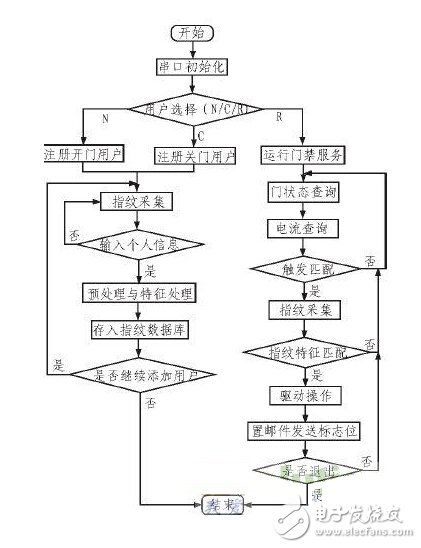
As shown in Figure 4, first initialize the serial port, open the serial device 0, 1, set the serial port parameters, restore the serial port unblocked state, and perform the user selection function after the serial port is successfully initialized: register the opening account or register the closing account or run the access control service [ N/C/R]. After selecting the system function N, the newly opened door user is registered, and the same fingerprint is acquired for 3 times. Compared with the traditional image acquisition, the problem that the registered fingerprint is not refined and the identification is not easy to identify is eliminated. After the fingerprint is successfully collected, the user's personal information is input, the new ID number from the upper computer database is registered, the user fingerprint information is stored in the database, and then whether to continue adding the user is selected. Similarly, the user selects the system function C to complete the operation of registering the closed user.
After the user selects the system function R, the access control service is run. On the one hand, the AVR queries the current door lock state, for example, assigns the door opening command to the matching state of the door. If the fingerprint matching operation FPI and the door match state are the same, the relay receives the AVR from the AVR. The door opening command drives the motor to perform the door opening action, and records the time at that time, adding a new user usage record to the local database and writing it into the log. In the same way, the closing command is executed. On the other hand, the AVR queries the current motor current level, and sends the real-time switch status of the door lock to the user by performing the switch door action and the current door lock motor current state by means of mail, realizing real-time monitoring of the door, greatly enhancing the access control system. safety.
2. Sending of alarm mail

Figure 4 System operation mode flow chart
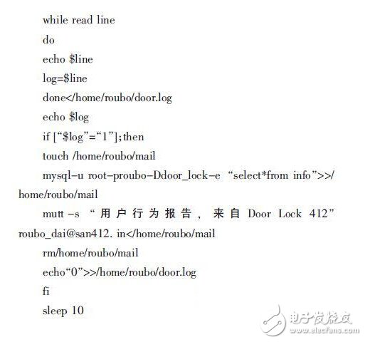
The ARM on the Raspberry Pi receives the query information from the AVR periodically to the access control state and current state through the RS 232 serial port, and writes a shell script program, which is transmitted to the mail sending module through the serial port by using wifi, and sends the alarm content to the specified user mailbox. It is time to monitor the status of the door lock. The procedure is as follows:

This part completes the function of packaging the information and sending the alarm content to the specified mailbox. The AVR periodically detects the state of the door and the current current state. When no one performs the opening and closing operation, the content of the door.log is “0â€. When someone performs the opening and closing operation or the current exceeds a certain value, the door.log content is “ 1", wherein the switch door lock includes two situations: one is that the registered user successfully realizes the switch door lock through fingerprint recognition; the other is that the unregistered user fails the fingerprint recognition but opens the door lock. The folder calls this data from the database and sends the data to the mailbox of the specified user, and then the door.log changes to "0" again, thus looping through the state of the gate.
The ARM on the Raspberry Pi receives the query information from the AVR periodically to the access control state and current state through the RS232 serial port, and writes a shell script program, which is transmitted to the mail sending module through the serial port by using wifi, and sends the alarm content to the specified user mailbox. The status of the door lock is monitored periodically.
Fourth, fingerprint identification access control system test
To verify the performance of the fingerprint recognition access control system, open the Linux program, register 4 different fingerprints, and then use different fingers for fingerprint recognition test. Observe the actions of the actuators when the fingerprint recognition succeeds and fails, and test 50 times. The contents of the email body of some system test results are shown in Table 1.

Table 1 System test result table
As can be seen from Table 1, the contents of the mail include ID, Name, AcTIon, and Date. The first seven lines are the registered users who successfully realize the switch door lock through fingerprint recognition, so their ID number and name information will be in the mail, and the last line of user fingerprint recognition fails but the door lock is opened, so the mail will be Their ID and name are set to NULL, alerting the administrator to pay special attention to the status of the door lock at the time to achieve the administrator's timing monitoring of the door status.
V. Summary
Based on the fingerprint identification technology, the FPI fingerprint identification module is combined with Linux to design a fingerprint identification access control system. One of the features of the design is based on the Linux operating system, establish a concurrent execution environment, improve CPU utilization, and use the Raspberry Pi master module and wireless. The communication module makes the whole structure simpler and has a significant improvement in system performance. Another feature is the timing detection of the door lock status and the use of wireless communication to send alarm messages to the user, greatly enhancing the security of the door lock. The practical test results show that the system runs well, can carry out reliable and safe fingerprint identification, and accurately and quickly complete the verification of personal identity to realize the function of opening and closing the door and the fast and timely mail alarm operation. In the subsequent work, the system can improve the stability of the existing program to improve the performance of the system to make the fingerprint door lock function more perfect.
Common Mode Coil For Automotive Product,Magntic Inductor Coil,Emi Common Mode Choke,CMC filter choke inductor
IHUA INDUSTRIES CO.,LTD. , https://www.ihua-magnetics.com