introduction
Yantai Hengyuan Biological Co., Ltd. is a national high-tech enterprise. It is currently the governing unit of China Bio-fermentation Industry Association. It relies on domestic key research institutes and universities, comprehensively applies biotechnology and fine chemical technology, and has advanced production process equipment and testing technology. The product quality meets the requirements of the US Food and Drug Administration FCCIV, and has obtained ISO9000 certification, ISO14000 environmental management system certification, ISO18000 occupational health and safety management system, OUKOSHER certification, HALAL certification, HACCP certification and feed additive production license. At present, the leading products are: fumaric acid, L-aspartic acid, L-alanine (industrial grade), L-alanine (medicinal food grade) to meet the needs of customers in different industries at home and abroad.
The company has two production lines of Phase 1 and Phase 2 with an annual production capacity of 10,000 tons. The oxygen in the air required in the production process is provided by the blower. Therefore, the blower is the main load that consumes electrical energy. Therefore, in order to realize the reasonable saving of electric energy in the power generation process, it is hoped that the first-stage blower can be energy-saving and dragged by the frequency conversion device.
2 centrifugal blower equipment introduction
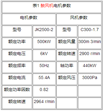
2.1 Motor and induced draft fan parameters

2.2 blower process requirements
The oxygen in the air required during the production process is provided by the blower. Therefore, the air volume of the blower directly affects the production process parameters. Therefore, the blower is an important component in the production process.
Therefore, on the one hand, the production process requires the inverter to be safe and reliable, stable and continuous, continuous and uninterrupted operation; simple operation, remote DCS control can be realized; frequency can be scheduled 2-50Hz; adapt to grid voltage fluctuation ability; protection function is perfect; The effect is obvious. On the other hand, the load is a centrifugal blower, which requires the inverter to be adapted to the large rotational inertia of the centrifugal fan when starting and stopping, reducing the influence on the grid voltage, and having the necessary protection for the motor, which helps to extend the motor. Service life.
After investigation and comparison of various high-voltage inverters at home and abroad, the Fengguang JD-BP37-500F (500kW/6kV) high-voltage inverter produced by Xinfengguang Electronics Co., Ltd. was selected as the control device of the blower.
3 new scenery JD-BP37-500F high voltage variable frequency speed control system
3.1 Principle of high voltage inverter system
3.1.l system composition

Figure 1 Structure diagram of high voltage variable frequency speed control system
Its system structure is shown in Figure 1. Fengguang high-voltage inverter is a high-high voltage source mode, which consists of a phase shifting transformer, a power unit and a controller. The front end is powered by a multi-winding isolated phase-shifting transformer, and each phase of the power unit is composed of a series of low-voltage power units. Input harmonics can meet the requirements of national standards for voltage and current distortion. The controller portion is controlled by a high speed microprocessor and communicates with the sub-microprocessor. The wind-light high-voltage inverter adopts modular design, good interchangeability, simple maintenance, low noise, small harmonic content, no torque ripple of the motor, and no special requirements for the motor.
3.1.2 Power unit circuit
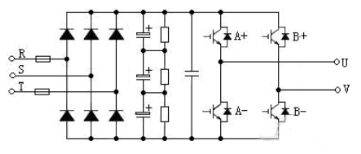
The circuit structure is shown in Figure 2. It is a basic AC-DC-AC single-phase inverter circuit, and the rectifier side is a six-band diode for three-phase full-wave rectification. The inverter side realizes inverter by performing sinusoidal PWM control on the IGBT inverter bridge. If a unit fails, the output of the unit can automatically control the IGBT bypass through software, and the whole machine can be derated, but it does not affect the operation. Each power unit is exactly the same and can be interchanged. This is not only convenient for debugging and maintenance. And the backup is also very economical.

Figure 2 unit circuit main circuit diagram
3.1.3 input side structure
The input side of the inverter is powered by a phase shifting transformer for each power unit. Each unit has its own independent three-phase input winding on the transformer. The power units are insulated from each other between the secondary windings of the transformer. The secondary winding adopts the extended-edge delta connection method to achieve multiplexing and reduce the harmonic components of the input current.
The secondary windings of the phase shifting transformer in this machine are divided into three groups, and multi-pulse rectification is adopted. This multi-stage phase-shifting rectification method can greatly improve the current waveform on the grid side, so that the power factor of the grid side under load is close to 1, and the harmonic component of the input current is low. The measured input current total harmonic component is less than 2%. In addition, due to the independence of the secondary winding of the transformer, the main circuit of each power unit is relatively independent, similar to the conventional low-voltage inverter, and it is easy to adopt the existing mature technology.
3.1.4 Output side structure
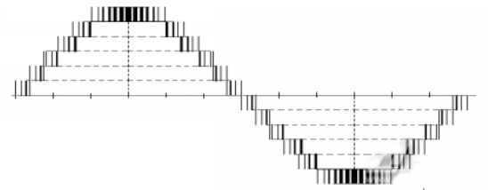
The output side is formed by connecting two output terminals of each unit in series, and the three-phase star connection output is supplied to the motor. By reorganizing the SPWM waveform of each cell, a staircase PWM waveform as shown in FIG. 3 can be obtained. This waveform has a good sinusoidality and a small dv/dt, which can reduce the insulation damage to the cable and the motor. The output cable can be made long without the need of an output filter. The motor does not need to be derated, and can be directly used for the modification of the old equipment. At the same time, the harmonic loss of the motor is greatly reduced, eliminating the mechanical vibration caused thereby and reducing the mechanical stress of the bearing and the blade.

Figure 3 Inverter output phase voltage ladder PWM waveform diagram
3.1.5 controller
The controller core is realized by high-speed DSP operation, and the well-designed algorithm can ensure the optimal running performance of the motor. The human-machine interface provides a friendly all-Chinese monitoring and operation interface, while enabling remote monitoring and networked control. The controller is used for the logic processing of the switch signal in the cabinet and the coordination with various operational signals and status signals in the field, which enhances the flexibility of the system. The controller and each control unit board use large-scale integrated circuits such as DSP and FPGA and surface soldering technology, and the system has extremely high reliability.
The multi-channel optical fiber communication technology is adopted between the controller and the power unit, and the low-voltage part and the high-voltage part realize true electrical isolation. The system has high safety and reliability, and has good anti-electromagnetic interference capability.
3.1.6 Control Power Supply
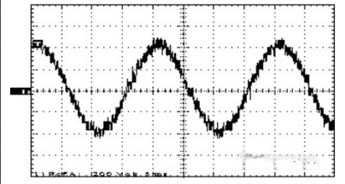
The third harmonic compensation technology is used to improve the power supply voltage utilization rate, and the modulation signal predistortion technology is utilized to make the voltage utilization ratio approximately 1. The system adopts advanced carrier phase shifting technology, which is characterized in that the fundamental waves of the unit output are superimposed and the harmonics cancel each other out. Therefore, the total output waveform distortion after series is extremely small. The theoretical output waveform after the superposition of multiple cells is shown in Fig. 4.

Figure 4 unit output superimposed waveform
Harvester Guide Rail,Harvester Conveyor Belts,Manure Spreader Accessories,Heavy Duty Clutch Plates
Changzhou Youeryou Trading Co., Ltd. , https://www.farmpartssupplier.com