With the continuous deepening of the range of ARM processor applications, ARM provides more and more peripherals according to different requirements. Common communication interfaces include RS232, RS485, CAN, and Ethernet. RS485 bus is widely used in various industrial occasions due to its long transmission distance, strong anti-interference ability and low price. Designed to use ARM9 processor S3C2440 internal integrated UART peripherals and RSM485 module to build RS485 bus interface with power isolation, electrical isolation, bus protection, through the modification of the embedded Linux system RS232 driver, so that after the modification When the serial port driver sends data, it automatically controls IO to realize the direction control of RS485 communication, which simplifies the control flow of RS485 communication. Under RS, the RS485 communication program realizes communication with other devices on the RS485 bus through reading and writing of the serial port.
1. Hardware design of communication interface
The S3C2440 processor integrates a wealth of peripheral resources on-chip to facilitate easy communication of various interfaces in embedded applications. The Samsung-ARM9-S3C2440 is used in the design, and its three UARTs are integrated on-chip. In the design, UART0 is used as the console interface of the embedded Linux operating system, and UART1 is used as the RS232 interface to communicate with other RS232 interface devices. UART3 Used as a data communication interface for RS485. Since the IO level of the ARM9 processor is different from the electrical standard of RS485, RS485 uses differential signal negative logic, +2~+6V means "0", -6~-2V means "1". In order to meet the electrical characteristics of the RS485 bus, external level conversion chips [1,3-5] must be used. Considering the harsh industrial application environment, factors such as power isolation, electrical isolation, and bus protection of the RS485 bus must be considered. The RSM485 module of Guangzhou Zhou Ligong was used in the design.
RSM485 isolated transceiver module is integrated power isolation, electrical isolation, RS485 interface chip, bus protection device. The module adopts potting technology and has good isolation characteristics. The isolation voltage is up to 2500VDC, supports up to 400 nodes, and the highest communication baud rate is 115200.
Figure 1 is a schematic diagram of a half-duplex RS485 bus using the UART2 in the S3C2440 in the system. At the same time, data can only be transmitted in one direction. The pin CON is the receiving and transmitting control pin, and is now connected to the IO pin of the S3C2440. The level of the pin controls the direction of the chip data. Set it to 0 when sending data, and set it when receiving data.
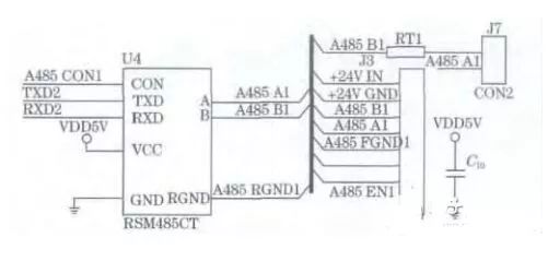
Figure 1S3C2440-485 interface
2. Software design
2.1RS485 communication design
In Figure 2, first open the serial port 2 modified by the driver part for RS485 communication, set its serial port parameters. At this time, the serial port 2 is in the RS485 bus receiving mode, and then send the data read command to the first device node on the bus to complete the select function call. After the SSC2440-485 interface is initialized, the select function waits for the device to return data according to the timeout time set by the user. If the select function returns an exception, it is re-initialized. If the data of the slave device is not accepted within the set time, select When the function returns a timeout, the next slave device waits for the timeout period, and sends the next device data read command, and re-enters the select wait device to return data; if the slave device returns data after the set time, then The serial port receives the buffer to read the data, completes the user protocol data parsing, completes the data communication of the master-slave device, and then polls the next device.
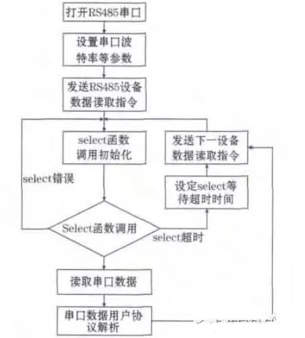
Figure 2 RS485 communication software flow
2.2RS485 driver design
The design uses the ARM9 processor S3C2440 integrated UART peripheral and RSM485 module built in. The driver has more control of the communication direction control pin than the RS232 driver, so in the Linux operating system, it can be used The serial port driver of the kernel adds direction control IO related code to achieve [4, 6, 7]. In the linux2.6.32 kernel source code, the serial port driver related code is in the file linux-2.6.32.2/drivers/seria/samsung.c. In order to realize RS485 communication, the modification part mainly includes three parts:
(1) Add the RS485 communication direction control IO port device initialization work in the initialization code of the serial port driver. The key code fragments are:
If(port-"line==2){//If the initialization is serial 2
S3c2410_gpio_cfgpin (S3C2410_GPH0, S3C2410_GPH0_OUTP); / / set GPG2, output function
S3c2410_gpio_setpin(S3C2410_GPH0,0);//Set to high level, so that the serial port is in the receive data state when it starts up.
The RS485 direction control IO port initialization uses two kernel functions (in arch/arm/plat-s3c24xx/gpio.c), and its function prototype is:
Voids3c2410_gpio_cfgpin(unsignedintpin,unsignedintfunc-TIon)
The function of this function is to set the function of the pin. The parameter pin is the pin to be set. Corresponding to GPH0 is the S3C2410_GPH0 pin. The parameter funcTIon is the function to set the pin. The output function is used in the setting. So the value is S3C2410_GPH0_OUTP.
Voids3c2410_gpio_setpin(unsignedintpin,unsignedintx)
The function of this function is to set the output value of the pin. The parameter pin is the pin to be set. The parameter x is the output value of the pin to be set to 0 or 1.
(2) Before the serial port data starts to be transmitted, set the direction control IO to 0, so that the RSM485 is in the transmitting state. The key code fragments are as follows:
If(port-"line==2){s3c2410_gpio_setpin(S3C2410_GPH0,1);//Set to low level, so that the serial port is in the receive data state when it starts up.
Udelay (30); / / wait direction IO control pin state stable}
After setting the direction to control the state of the IO port, add a certain delay, wait for the direction IO control pin state to be stable, and avoid sending data errors due to unstable direction control state.
(3) After the serial port data transmission is completed, it automatically enters the data receiving mode, and the key code fragments are:
If(port-"line==2){
While(!(rd_regl(port,S3C2410_UTRSTAT)&0x04));//Wait for the serial port to be sent, this sentence must not be less
S3c2410_gpio_setpin(S3C2410_GPH0,0);}
Because the S3C2440 processor comes with a serial port with a hardware buffer, the serial port driver, the data transmission is completed, the data has been written to the driver in the driver, but the serial data is being sent out, so you must wait for the data. After the complete transmission is completed, set the direction control IO port to 1.
2.3 Linux RS485 communication programming
After the RS485 driver is modified, the RS485 interface can be operated like the serial port. In the embedded Linux system, the device files of the serial port are located in the /dev directory, and the RS485 device can be directly operated by using the file open and read/write functions [2, 8, 9]. Some key code snippets for device open and read and write are:
Intfd=open(Dev, O_RDWR|O_NOCTTY);//Open the device...
Nread=read(fd,s1_buf,64);//Read device data...
Write(fd,send_buff,6);//write send data
In the design, ARM9 as the main control device of RS485 communication communicates with a slave device. When the master device reads data from each slave device, the master device first sends a data read command to the device, and then the device waits for the slave device to return. data. Therefore, in practical applications, the waiting time for waiting for data to be returned from the device is reasonably set. In the design, use the select function to achieve the wait delay, the key code is:
Switch(select(max_fd,&fds,NULL,NULL,&TImeout))//select
{case-1:break;//select error, exit the program
Case0: Find_endp(&pth_endp_line1);
Send_buff[1]=pth_endp_line1.index+1;
Send_buff[4]=send_buff[1]+1;
Write(fd1,send_buff,6);
TImeout.tv_sec=time1;
Timeout.tv_usec=time2;break;//timeout, poll again
Default:if(FD_ISSET(fd1,&fds))//Serial 1 data
{nread=read(fd1,s1_buf,64);
If(nread)=20)
{i2c_led_set(8,1);
Value_t=myrount(Value_t,100);
Value_h=myrount(Value_h,100);
Value_p=myrount(Value_p,100);
Value_pt=myrount(Value_pt,100);
}}}//endswitch
3 experimental results and applications
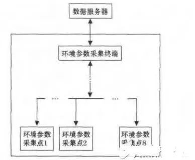
Figure 3RS485 interface application
The design is successfully applied to the environmental parameter acquisition system. The system mainly consists of an acquisition node, a collection terminal, and a data server, as shown in Figure 3. The collecting node is responsible for collecting the air pressure, temperature and humidity parameters; the collecting terminal reads the collected data from the respective collecting nodes through the RS485 bus, and reports the collected data to the data server through the Ethernet; the data server completes the data storage, and is other Formal applications provide an application interface. In the design, the master device polls all the devices on the RS485 bus, and the master control device ARM sends a data read command every 1s. The read command contains the slave device identification code, and the slave device that meets the identification code immediately returns the collected data. . If the data is corrupted, the master will discard the packet and wait for the next poll, so the packet error retransmission mechanism is not considered in the communication program design. The design achieves the desired goals. Although there are occasional errors, the design avoids the modification of the complex code of the Linux kernel, and it is still a practical design method.
Ring Type Connecting Terminals
Ring Type Connecting Terminals,Terminals,Connecting Terminals
Taixing Longyi Terminals Co.,Ltd. , https://www.longyicopperterminals.com