Portable electronic products use batteries as power sources. With the rapid development of portable products, the amount of various batteries has increased significantly, and many new batteries have been developed. The high-energy density lithium-ion battery developed in recent years has the characteristics of small size, large capacity, and long standby time, and is very suitable for the application of portable systems.
In the design process of portable electronic products, the design of its power management module is very important, because it is related to the stability, continuity and rapid recovery of the entire system. Especially when using a lithium battery as the system power supply, the role of its power management module is more prominent. This article introduces a power management module solution for portable electronic heart sound detector based on bqTINY-II for the characteristics of lithium battery charging.
1 Lithium-ion battery charging process
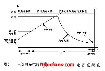
The charging process of lithium series (lithium ion or lithium polymer) batteries is divided into three stages, as shown in Figure 1.

The first stage is the inspection and pre-charging stage. The main tasks at this stage are: verify the temperature of the battery and adjust it to a range suitable for rapid charging; detect the battery voltage and raise it to a safe level. Temperature inspection and pre-charging improve the safety and service life of the battery.
The second stage will be constant current charging with "1C" or slightly lower current. Once the battery reaches its voltage limit of 4.1V or 4.2V, it has finished charging about 70% of its capacity and entered the third stage of charging.
The third stage is to charge the battery at a constant voltage. In order to maximize safety and power, the charging voltage needs to be stabilized within an accuracy of ± 1%. In the constant voltage charging stage, the charging current gradually becomes smaller, and in most cases, when this charging current is close to 10% of the fast charging current, that is, C / 10, the charging process ends.
2 Power management module based on bqTINY-II
bqTINY-II is a battery charge management chip launched by TI, which brings a set of integrated solutions for power system designers. The chip integrates functions such as automatic power supply selection, power FET and current sensor, high-precision current stabilization and voltage stabilization capability, charging status display and charging suspension. An important feature of it is that it can choose between two charging modes and supports the current popular USB interface charging.
bqTINY-II supports three stages of charging procedures as shown in Figure 1, including the pre-charge adjustment stage, the constant current charging stage and the high precision constant voltage charging stage required by many equipment manufacturers. The power consumption of bqTINY-II is extremely low. When the system is not connected to the power supply, bqTINY-II will enter a low-power sleep mode, and it will only draw very little power from the battery at this time.
2.1 Schematic circuit diagram
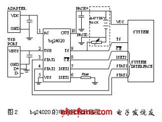
The schematic circuit of this scheme is shown in Figure 2. The schematic diagram takes the BQ24020 chip as the core and is equipped with necessary peripheral components. Due to the high integration of the BQ24020 chip, the peripheral components required are greatly reduced, requiring only 3 filter capacitors and 1 resistor for setting the AC precharge rate.

The power management module shown in Figure 2 has 4 input interfaces, 4 output interfaces, and a common ground. Among them, 4 input interfaces are: AC adapter AC interface, USB power supply interface, charging enable signal CE, USB charging point setting; 4 output interfaces are: power output, power temperature signal output, and 2 charging status indication output.
The parameters of the six interfaces for the application system are as follows:
VCC is the battery voltage output port, and this power module outputs current through this port to supply power to the application system.
TS is the output of the power supply temperature status signal, which is generated by a 10kΩ negative temperature coefficient thermistor in the battery compartment. The application system can determine the current temperature status of the power supply by comparing the voltage of the interface with the power supply ground.
CE is the enable control signal of the bqTINY-II chip. When the signal is at a low level, the charging circuit works. At a high level, the chip stops working and enters a low-power sleep mode.
The ISET2 interface is used to control the parameter selection during USB charging. Because the USB interface is divided into high-power (500mA) and low-power (100mA), the system must recognize it. After the recognition is completed, the system can send a low-level signal to the interface, so that the chip selects 100mA mode for charging or sends a high level to select 500mA. If the system does not want to use USB mode for charging, you can set the interface to a high-impedance state.
STAT1 and STAT2 are the output signals of the charging status display. This signal can directly drive multiple LEDs for status indication or sent to the main processor for further processing.
Fiber Optic Components,Parts Of Fiber Optic Cable,Fibre Optic Connector,Parts Of Optical Fiber
Cixi Dani Plastic Products Co.,Ltd , https://www.cxdani.com