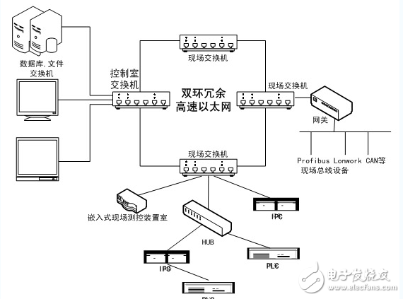
The on-site intelligent monitoring device is the basis and key for building a control network. The development of Ethernet field smart devices using high-end embedded technology is an important development trend. This paper proposes a monitoring system based on embedded industrial Ethernet technology, and elaborates the hardware and software design process of embedded industrial Ethernet monitoring device, including the implementation of 32-bit microprocessor system, the implementation of Ethernet interface unit module, uCLinux Analysis and porting of embedded operating systems, analysis and implementation of drivers under uCLinux, Socket socket analysis, HTTP protocol analysis, implementation of embedded Web servers, etc. This paper designs a dual-ring redundant high-speed industrial monitoring network system based on Ethernet. The system structure is shown in Figure 1.
Embedded Industrial Ethernet Monitoring System Hardware
Embedded system hardware includes microprocessors, peripheral control circuits, read-only memory, readable and writable memory, and peripherals. This article will introduce and analyze the self-developed embedded Ethernet monitoring system device. The device uses the 53C4510B embedded microprocessor as the core, and uses the MAX1422 as a 12-bit high-speed AD converter to connect the RTL82OIBL Ethernet physical layer interface circuit, plus SST39VF160 and HY57V641620. As a FlashROM and SDRAM unit, it constitutes a basic hardware platform.

Figure 1 Schematic diagram of dual-ring redundant high-speed Ethernet
RS-232 serial communication interface
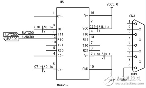
The RS-232 serial interface circuit is used for the peer-to-peer connection between the embedded microprocessor serial module and external serial resources to realize the conversion between LUTTL level and RS-232 level. This paper uses a RS-232 serial port circuit. . Figure 2 shows the RS-232 serial interface circuit diagram. The data transmission signal UATXD0 of UART0 is connected to T11 of MAX3232E. After being converted to RS-232-C level, it is connected to the RXD pin of the 9-pin plug by T10. The TXD signal of the 9-pin plug is connected to R11 of the MAX3232E, converted to LVTTL level, and connected to the data receiving pin UARXD0 of UARTO by R10.

Figure 2 RS-232 serial interface circuit diagram
Storage unit design
The memory unit circuit is composed of a large-capacity F1ashROM and SDRAM. According to the working mode of the embedded system, the system first uses the Boot Loader code to copy the operating system kernel and application program in the FlashROM into the SDRAM, and performs memory relocation, and then jumps to the address execution program corresponding to the SDRAM. The S3C4510B supports 8-bit/16-bit/32-bit memory banks, which can be used to build 8-bit/16-bit/32-bit F1ashROM memory systems. The wider the memory data bus, the higher the performance of the system. However, considering the factors such as cost and power consumption, the design uses a SST39VF160 to form a 16-bit F1ashROM memory system, a memory of about 700kB size of the uClinux kernel and other applications. Referring to the working characteristics of S3C4510B, the design uses two HY57 V 641620 to construct a 32-bit SDRAM memory circuit in parallel, and fully utilizes the data processing capability of the 32-bit CPU to meet the requirements of the embedded operating system and various complex applications.
Based on the development trend of establishing seamless enterprise information integration, 32-bit embedded processor system and industrial Ethernet technology, the design scheme and focus of high-performance embedded industrial Ethernet monitoring system proposed in this paper. The hardware architecture and embedded software system of the new embedded industrial Ethernet monitoring device are analyzed and implemented.
Universal Back Sticker, Back Film, TPU Back Sticker, Back Skin Sticker, PVC Back Sticker, Back Skin,Custom Phone Sticke,Custom Phone Skin,Phone Back Sticker
Shenzhen Jianjiantong Technology Co., Ltd. , https://www.jjthydrogelprotector.com