The solid material will melt when heated to a high enough temperature and then evaporate into a gas. Some materials even directly transform from the solid phase to the gas phase. This process is called sublimation or ablation. The heating temperature of the material is high enough and significant material removal will also occur. Today, let’s take a look at how to model this process using COMSOL Multiphysics®.
Use ablation to remove material
When a solid material is heated, the temperature will rise and eventually a phase change will occur. This process involves conversion to the liquid phase and then to the gas phase, or directly to the gas phase. Since our goal is to remove materials, we only consider materials that are directly converted to the gas phase.
Let us further assume that the maximum temperature of the surface rises when the material is heated, while the interior is heated, but the temperature is not so high that the solid is directly converted into the gas phase. Therefore, we only discuss the situation where sublimation occurs on the surface of the material. At the same time, it can be assumed that when the material is transformed into the gas phase, it no longer absorbs a lot of heat. This assumption is reasonable when there are other air currents around to carry away the evaporated material. The process of heating the surface of the material to a gaseous state and quickly removing the gas surrounding the solid is called ablation.
For ablation to occur, the surface of the material must absorb a large amount of heat flux. Among such heat sources, one of the most practical examples is the laser. This method has been widely used in various industries, including laser processing, surgery and laser engraving, among other applications. Of course, the heat source may not be a laser. In fact, ablative thermal shielding has been used to assist the aircraft to withstand the high thermal loads generated when it re-enters the atmosphere.

The heat shield on the reentry vehicle drawn by a painter.
Ablation modeling requires setting up and solving a model that calculates the temperature change of solid materials over time, while taking into account the heat of sublimation and the resulting material removal. First, a thermal boundary condition must be set to ensure that the temperature of the solid material does not exceed the sublimation temperature. Second, a method must be developed to model quality removal in the relevant domain. Let's take a look at how to accomplish these two tasks in COMSOL Multiphysics.
Modeling thermal ablation in COMSOL Multiphysics
First, we consider building a highly simplified model for the thermal shielding on the aircraft shown above. It is assumed that the heat flux distributed on the heat shield is consistent in time and space. Another assumption is that the material properties of the thermal shield do not change, and the temperature change on the shield plane is negligible compared to the temperature change along the thickness. Under these two assumptions, we can simplify the model into a one-dimensional domain, as shown in the figure below.
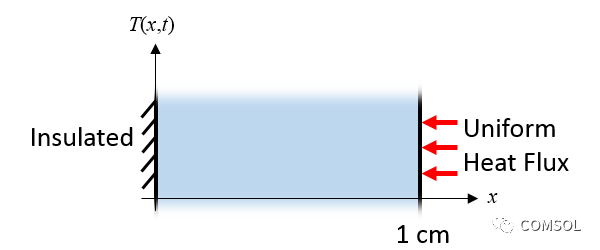
The heat shield with consistent heat flux (in the previous figure) can be simplified into a one-dimensional model.
The thermal boundary condition of the one-dimensional domain starts with the thermal insulation condition on one side, which means that the aircraft fuselage does not exhaust heat. The heat flux on the other side is uniform and fixed, similar to the effect of atmospheric heat transfer when returning to the atmosphere.
Finally, we need to add a set of boundary conditions to simulate the heat loss caused by material ablation. When the material temperature reaches its ablation temperature, it transforms into a gaseous state and is removed from our modeling domain. Therefore, the temperature of a solid material cannot be higher than the ablation temperature. When the temperature of the material reaches its ablation temperature, the surface will lose a certain amount of quality, depending on the density of the material and the heat of sublimation. In order to model this solid material, we need a thermal boundary condition and a way to model material removal.
The thermal boundary condition we introduced for ablation modeling is an ablation heat flux condition, which has the form:
(1) 
among them, Indicates the heat flux absorbed by the ablation of the material,
 Represents the ablation temperature,
 Represents the heat transfer coefficient related to temperature,
 When is zero,
 Time showed a linear increase.
The slope of this curve is steep, which ensures that the solid temperature cannot significantly exceed the ablation temperature. In addition to thermal boundary conditions, we must also add material removal. The erosion rate of the solid boundary is:
(2) 
among them, Indicates the ablation rate of the material,
 Indicates the density of the material,
 Indicates sublimation fever.
Let's take a look at how these two equations are implemented in COMSOL Multiphysics. We start with material properties and thermal loads and define them through global parameters, as shown in the figure below.
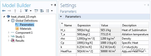
"Global parameters" applied to a one-dimensional model.
Next, use the ramp function to define the required temperature-dependent heat transfer coefficient in equation (1), as shown in the screenshot below. The slope itself can be any value, but too small a value will exceed the ablation temperature, and too large a value will cause the value to converge too slowly.
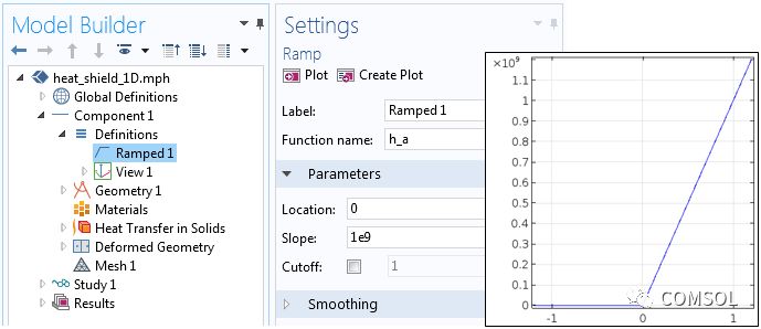
The slope of the "slope" function is steep.
Our model contains a one-dimensional domain with a length of 1 cm. The Heat Transfer in Solids interface is used to model changes in temperature over time. The incident heat flux is applied to one side, and the thermal insulation condition is applied to the other side. The screenshot below shows the achieved ablation heat flux equation (1). Because the heat flux condition is introduced, the ablation heat flux in equation (1) is the sum of the incident heat flux and the ablation heat flux applied to the boundary.
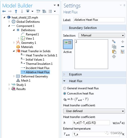
The realization of the ablation heat flux condition in equation (1).
To simulate the removal of material, you can use the deformed geometry interface. The free deformation function allows the size of the domain to be changed as specified by the boundary conditions. On one side (insulating side), the specified deformation ensures that the boundary does not shift. At the other end of the domain, specify the normal mesh velocity condition and execute equation (2), which is the material removal rate, as shown below.
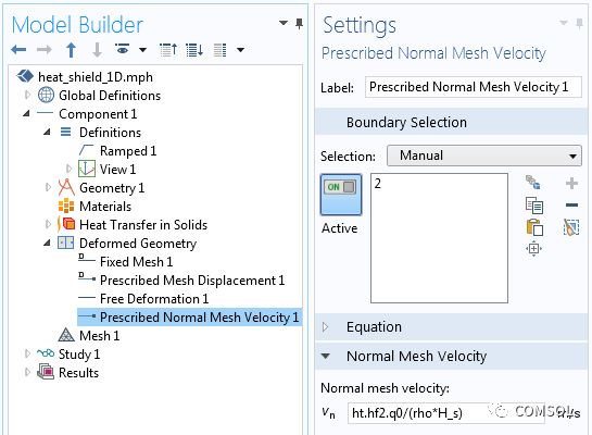
The material removal in equation (2) is realized using the deformed geometry interface.
The expression of the grid velocity is ht.hf2.q0/(rho*H_s), where ht.hf2.q0 represents the heat flux calculated by the previously defined "ablation heat flux" boundary condition. You can go to Results>Report>Complete Report to find all such internally defined COMSOL variables at any time.
Through these functions, we have obtained the ablation effect and can solve the model of temperature change with time, as shown in the figure below. We can observe that the temperature on the right side of the solid rises to the ablation temperature and material starts to be removed from the domain. Although the material boundary is ablated, the temperature remains the same. Also note that once the material starts to ablate, the position of the temperature derivative will change, which means that the total heat flux is also changing.
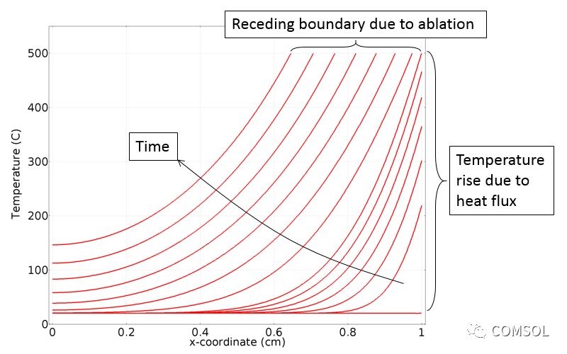
A one-dimensional domain of temperature changes over time.
At the end of the discussion, let us show the results of a more complex problem. The problem involves an axisymmetric geometry on which the thermal load is a Gaussian intensity curve. Our focus is to simulate the burning of the material by laser heating to create a hole. We can use the exact same model settings described above, but in a two-dimensional domain.
The animation below emphasizes the simulation results, showing the formation of holes over time. The domain changes are very obvious, so in this example, the Deformed Geometry interface uses the hyperelastic smoothing type to deform the mesh. Note that the deformed geometry interface does not allow any topological changes in the domain. Therefore, we cannot simulate the formation of through holes, only the removal of material on one side.
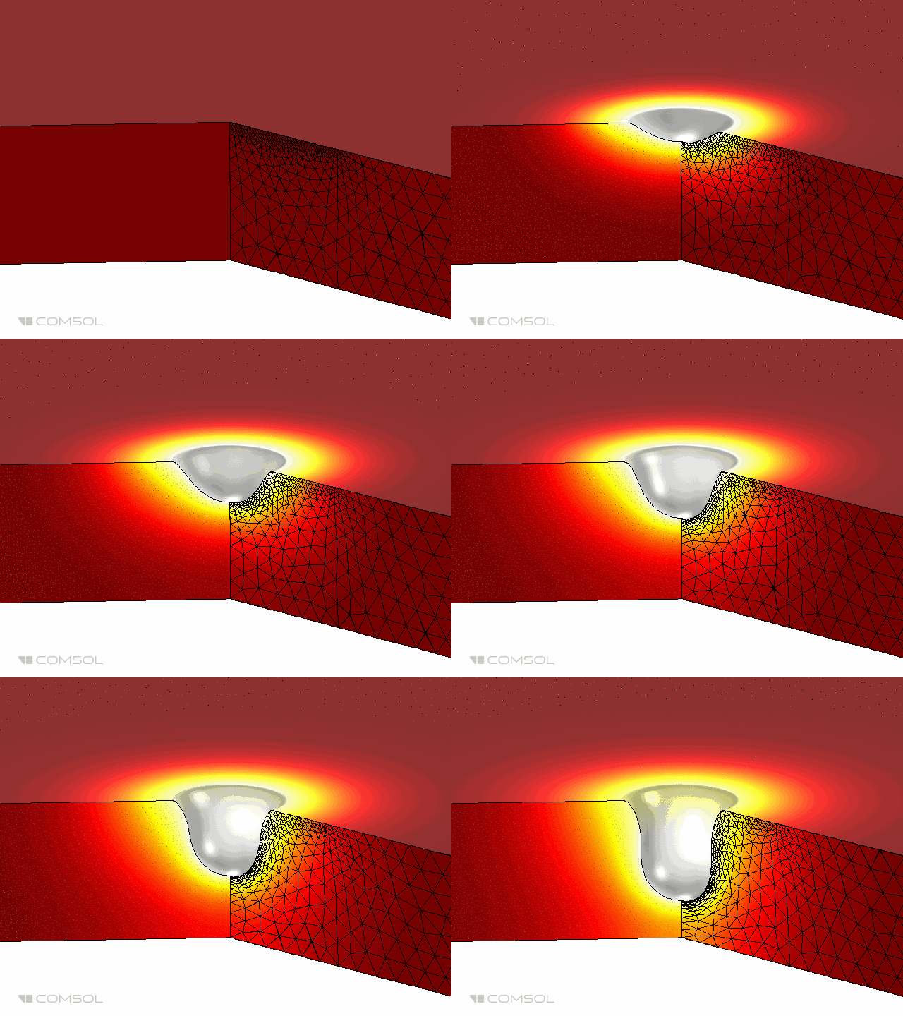
The animation above shows laser burning in a two-dimensional axisymmetric model.
Concluding remarks on thermal burn modeling
In today's article, we demonstrated how to use the "Heat Flux" boundary condition and the specified mesh velocity function in the Deformation Geometry interface to model the burning of materials. The examples presented are always as simple as possible so that we can focus on the modeling of the burn. A more realistic model should also include radiative heat transfer from the surface and temperature-related material properties.
Moreover, pulse thermal load can also be considered, which is a common load in laser processing. When heating with a laser, light may penetrate a certain distance in the material. In this case, you might be able to use Beer-Lambert's law to model energy deposition compared to other methods of material laser heating modeling.
Variable Frequency AC Power Supplies
The VFP series AC Power Supplies are high precision, high efficiency, low THD adjustable AC power supplies that converts the input mains power through AC→DC→AC conversion, and gives a pure sine wave AC output with adjustable voltage & frequency within a certain range. Also known as Variable Frequency AC Power Source.
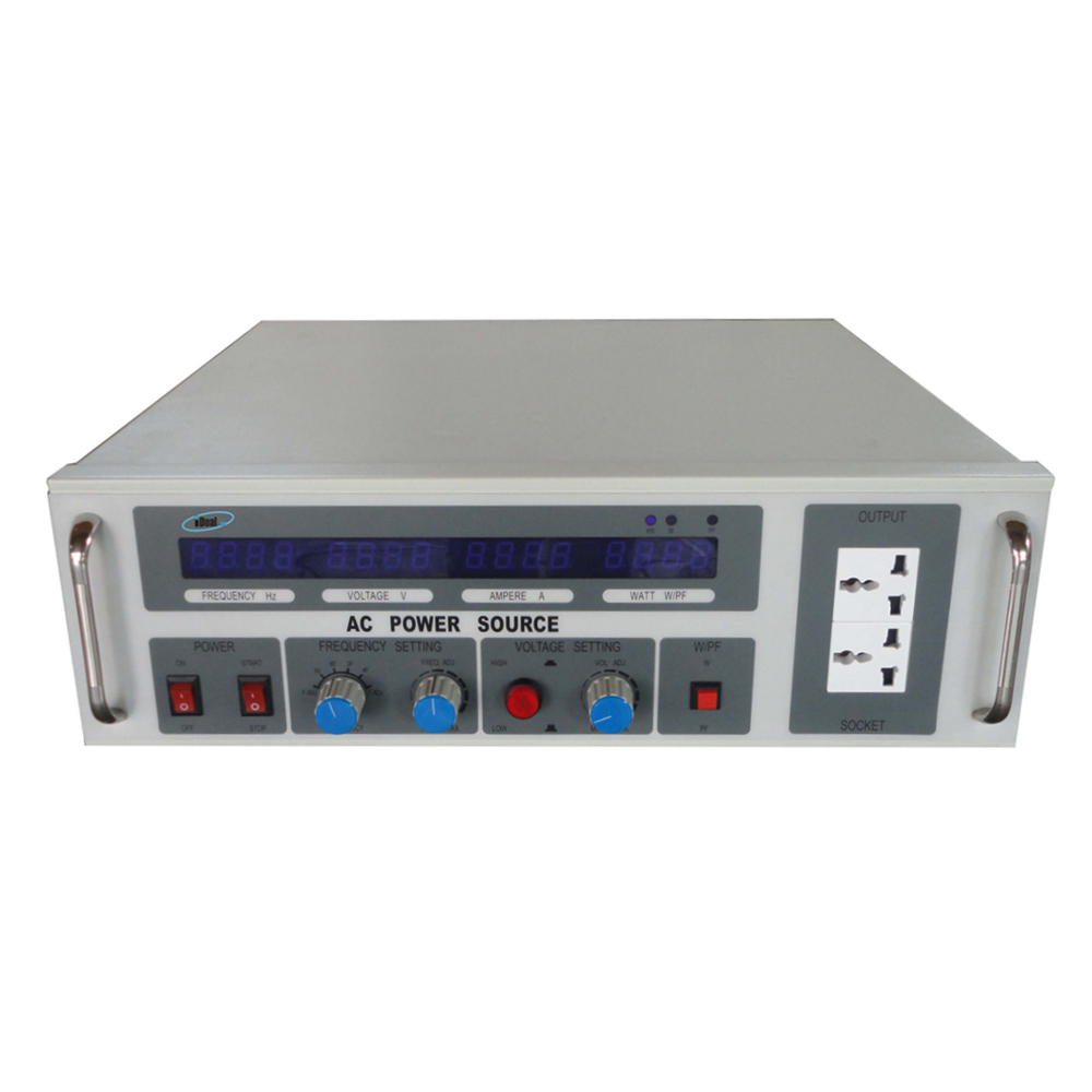
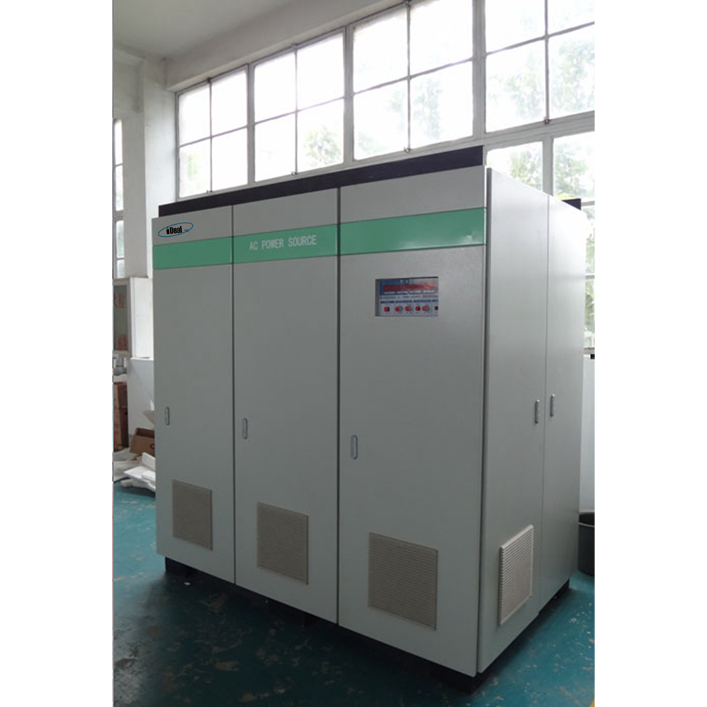
According to the difference in the number of output phases, it can be divided into single-phase and three-phase AC power supplies.
The output power of single-phase adjustable AC power supply ranges from 500VA to 200KVA, the output power of three-phase adjustable AC power supply ranges from 3KVA to 600KVA, the output voltage is divided into 0 ~ 150Vac, 150 ~ 300Vac, and the output frequency is adjustable from 45Hz to 70Hz with 50/60Hz fixed frequency output.
Through the friendly operation panel, you can read the output data such as output voltage, output current, output power, power factor, etc., providing accurate data records for your test, and can add RS485 interfaces as standard, following the MODBUS-RTU international communication protocol, which can realize remote control and operating status monitoring of the power supplies.
This series of adjustable AC Power Supplies have comprehensive protection functions, such as: over voltage, over current, over temperature and short circuit protections, which can protect the AC power supplies and DUT from damages. At present, it is mainly used for Various electrical appliance manufacturers conduct grid simulation tests on electrical appliances according to the voltage/frequency requirements of different countries. Imported electrical appliances are used for the domestic demand for variable voltage and frequency conversion, as well as various AC motors and AC transformers.
Variable Frequency AC Power Supplies, AC Variable Frequency Power Supplies, Variable Frequency AC Power Sources, Variable Frequency Power Supplies, Variable Frequency Power Sources
Yangzhou IdealTek Electronics Co., Ltd. , https://www.idealtekpower.com