In the new automotive electronics applications, the fastest change in signal format is video. A few years ago, video displays in in-vehicle devices were limited to small-sized displays in navigation systems. Rather, it was just a navigational electronic device, and some luxury cars used the same display to play television signals. The video signal needs to be transmitted over a considerable distance from the television receiver to the display output. The image format is an analog signal called a composite video baseband signal (CVBS).
This article refers to the address: http://
In recent years, with the development of automotive electronics technology, research and development on video sources, display devices and video transmission lines have made great progress. For example, the navigation display can be separated from the electronic system so that the display can be mounted in a position that is convenient for the driver to observe. This separation requires an increase in the video transmission line.
In addition, more and more display devices are installed on cars today, including electronic dashboards for displaying speed, speed, and car status, as well as rear-seat multimedia players (passengers can watch TV or DVD, etc.). Video transmission lines are required for each display. A new generation of cars may also be equipped with a variety of cameras for assisted driving, such as rearview mirror cameras, night vision goggles, and road sign recognition cameras, each of which requires a video transmission line to connect to the display device.
The rapidly increasing transmission lines inside the vehicle body, especially the longer and longer these transmission lines, make transmission of analog CVBS signals very difficult. These signal formats cannot withstand electromagnetic interference from automobiles. In addition, large screen displays and increasingly higher resolutions further exacerbate video interference (such as multipath interference).
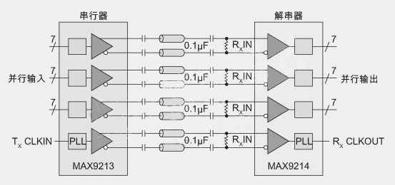
Figure 1: The first-generation LVDS transceiver has eight outputs that can be connected to the navigation display using an LVDS transmitter/receiver.
One solution to reduce video interference is to replace the analog signal with a digital signal that does not itself interfere. Low voltage differential signaling (LVDS) has proven to provide the most reasonable connection for digital video transmission. The small signal amplitude (0.35V) and differential structure allow the LVDS transmission line to have minimal electromagnetic radiation.
The first generation of LVDS transmission devices (such as the MAX9213, MAX9214) have been installed in the car to provide one clock output and three channels of data, using the LVDS transmitter/receiver to connect to the navigation display (Figure 1). The three-way parallel output requires the rate required for image transmission, and the clock is used for isochronous transmission.
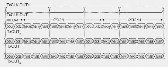
Figure 2: In the DC-balanced LVDS data output format, every 7 parallel data bits are a group, and each group has 2 additional bits to indicate whether the data is inverted.
An important feature of the first generation system is the choice of output capacitive coupling, which avoids the ground potential difference between the transmitter and the receiver, which can sometimes be on the order of a few volts. If DC coupling is used, the potential difference may make the data transmission completely impossible, or even generate a very large current, thus damaging the circuit. If capacitive coupling is used, care must be taken that the data cannot be charged for a long time in one direction of transmission, and this can occur when a long string of "1"s is transmitted.
The "DC Balance" circuit inside the MAX9213/MAX9214 solves this problem. When it detects a long string of "0" or "1", it will be inverted before sending the data. Each 7 parallel data bits are a group, and each group has 2 additional bits to indicate whether the data is inverted, as shown in Figure 2. When the data arrives at the receiving end, the receiver restores it to the original data. In order to avoid overcharging of the capacitor, the transmitter needs to inform the receiver whether the data has been inverted.
The drawback of the first generation LVDS devices was that four pairs of twisted pairs were required to achieve the required data rate, so that the eight data lines complicate the mechanical structure. Second-generation LVDS devices have been improved, such as the MAX9217 and MAX9218, which use a pair of twisted-pair wires to simultaneously transmit data and clocks.
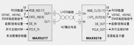
Figure 3: Block diagram of the video and control data link setup and connections between the MAX9217 and the MAX9218.
The MAX9217 serializer features a 27-bit parallel input with a bus speed of up to 35Mbps. Among these 27 bits, 18 bits are video RGB data, in which 3 primary colors each occupy 6 bits, and the remaining 9 bits are control signals. The first 3 bits of the 9-bit control signal are designated for vertical, horizontal, and RGB data synchronization: VSYNC(C0), HSYNC(C1), and ENAB(C2). The remaining six control bits (C3 to C8) are used for other control signals.
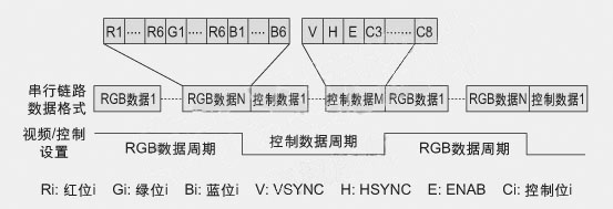
Figure 4: Video data and control data format for the serial link.
In this example, we use a portion of the 6 control bits to transmit audio data. The MAX9217 converts 18-bit RGB data or 9-bit control data into serial data and transmits it over an LVDS link. The control data is transmitted during the blanking period of the video display and is indicated by the RGB data enable signal (ENAB). After receiving the serial data, the MAX9218 converts it to the same parallel data as the MAX9217 input format. Similarly, when the MAX9218 outputs parallel data, the bus clock is regenerated based on the timing of the serial LVDS link. Figure 3 is a block diagram of the video and control data link setup and connections between the MAX9217 and the MAX9218. Figure 4 shows the timing of video data and control data. Depending on the video format, display resolution and link rate, the control duty cycle of RGB data is between 1% and 5%.
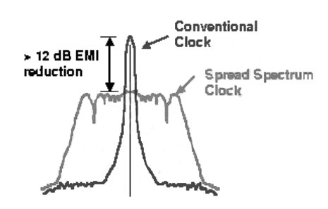
Figure 5: Spread spectrum technology reduces EMI.
Using a pair of transmission lines for high-speed data and clock transfers, these devices can transfer more data than first-generation devices. Maxim's upcoming devices will reach 42MHz and 1.15Gb. An increase in the clock frequency results in stronger electromagnetic radiation, and spread spectrum transmission techniques can be used to reduce EMI. Spread spectrum technology adds jitter to the clock frequency, spreading the original EMI peak energy over a wider frequency band. Since the energy is constant, the maximum peak of EMI is reduced (Figure 5).
The second generation of LVDS data transmission devices are primarily designed for large screen applications. The connection of various cameras inside the car does not require high transmission speeds. For this application, Maxim's third-generation LVDS devices use a low clock rate and reduce the width of the parallel data bus. Third-generation devices are used to control the transmission of data and can be used to set display brightness and contrast, or camera sensitivity. Currently, CAN, LIN or UART transmission buses are used in the system. These solutions require more devices and cables, and occupy a large space and a high cost. Maxim's third-generation devices will use the LVDS interface to transfer control data while avoiding other interfaces.
Docking station
Docking stations for laptops are meant to bridge the gap between portability and having a stationary place to work and play.With a docking station,you can get the best of both worlds with a system that allows your laptop to work for both purposes.Some of the most basic docking stations provide a power supply and ports for connecting to other devices.More advanced docking stations may inclade space for additional PC monitors,keyboards,and computer speakers.It can also have additional USB-C ports to connect to printers,add external hard drives,and connect microphones and audio.
Docking Station,Macbook Docking Station,Macbook Pro Docking Station,Usb C Docking Station
Pogo Technology International Ltd , https://www.pogomedical.com