Commonly isolated and non-isolated topologies for LED general-purpose lighting applications powered by AC-DC power. The so-called "isolation" refers to the electrical isolation between the input and output using a transformer or the like. Both of these topologies have their own characteristics. In comparison, the advantages of non-isolated topologies include smaller magnetic components, higher energy efficiency, fewer component counts, lower total bill of materials costs, and mechanical design to meet safety regulations. ON Semiconductor offers a variety of non-isolated high power factor LED driver solutions that provide higher energy efficiency and compact design for different low and medium power LED general lighting applications such as linear fluorescent replacement and high power downlights and spotlights. .
Common buck non-isolated application application LED driver solution
In applications such as MR16 bulbs, 12 V landscape lighting, solar-powered LED lighting and billboard text circuits and logo backlights, the flexible step-down driver NCL30160 can be used. This device is an energy-efficient, peak-current-controlled buck controller for single-voltage inputs, providing an excellent solution for space-constrained and energy-efficient applications such as MR16 LED bulbs. But strictly speaking, the NCL30160 is a DC-DC non-buck isolation driver solution.
ON Semiconductor's NCP1015 self-powered monolithic switch control ICs are available for 1 to 8 W low power LED lighting applications such as G13, GU10, PAR16, PAR20 and recessed lights. The device integrates a 700V high-voltage MOSFET in a PDIP-7 or SOT-223 package to provide all the features needed to build a robust, low-cost AC-DC LED power conversion solution. This device can be used in both isolated and non-isolated solutions to meet different application requirements. Among them, the NCP1015-based non-isolation scheme uses a tapped inductor to isolate the AC signal, improve the duty cycle of the MOSFET, improve system energy efficiency and circuit performance, and achieve a power factor greater than 0.7 by reducing the capacitance or valley fill circuit.
In lighting applications, LED drivers face power factor correction (PFC) problems if the output power requirement is above 25 W. For example, in the solid-state lighting standard of the US “Energy Star†project, there is a mandatory requirement for PFC (regardless of the power level), that is, the power factor is higher than 0.7 for residential applications, and the power factor is high for commercial applications. At 0.9. In this type of application, ON Semiconductor's NCP1607 Critical Conduction Mode (CrM) scheme can be used for both isolated and non-isolated solutions.
High power factor non-isolated LED scheme supporting dimming
Some AC-DC non-isolated LED lighting applications require both high power factor and support for dimming, such as analog, digital (PWM) or triac dimming (TRIAC) dimming. In these applications, customers can use ON Semiconductor's NCL30000 power factor correction TRIAC dimmable LED driver or LV5026/29 series high power factor dimmable LED driver.
I. NCL30000/2 non-isolated dimmable high power factor LED driver topology and application
The NCL30000 is a power factor correction dimmable LED driver for LED lighting applications such as residential and commercial lighting. The NCL30000/2 is available in a compact 8-pin surface mount package that uses a critical conduction mode (CrM) flyback architecture to provide a high power factor greater than 0.95 in a single-segment topology, eliminating DC-DC Conversion segment. Typical applications include LED driver power supplies, LED downlights, triac TRIAC dimmable LEDs, and power factor corrected constant voltage power supplies. This device is compatible with leading edge TRIAC dimmers and trailing edge transistor dimmers. Depending on the dimmer used, the LED output can be adjusted down to 2%.
The NCL30000 operates with a constant on-time CrM and is ideal for isolated flyback applications, but can also be configured as a non-isolated high power factor topology. In the non-isolated topology, the NCL30002 has higher current accuracy (±3.1%) at operating temperatures from -40 to 125°C, including different options for buck and buck-boost topologies, as described below. Comparison.
1) NCL30000 non-isolated buck and buck-boost topology comparison
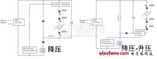
In terms of topology, the disadvantage of the buck topology is that the input current waveform is dependent on the output voltage. In this configuration, since the inductor and the LED string are arranged in series, current flows only when the input voltage exceeds the forward voltage drop (VF) of the LED; CrM and constant on-time operation provide high power factor; direct sensing LED current; low loop bandwidth supports high power factor operation; MOSFET current is equal to LED peak current; MOSFET voltage stress is equal to peak mains voltage; power factor (PF) and total harmonic distortion (THD%) performance depends on output voltage drop and The ratio of input voltage (VF/Vin), the higher the ratio, the lower the PF; the higher the ratio, the higher the THD.

Figure 1: Comparison of Buck and Buck-Boost Configurations
In comparison, the input current waveform of the buck-boost topology is load-independent, with high power factor and good total harmonic distortion performance. In the buck-boost configuration, the inductor is not connected in series with the LED string. The input current waveform or distortion is independent of the output voltage drop (VF). The inherent LED fault protection provides protection when the MOSFET is shorted; the LED forward voltage drop can be Above or below the input voltage; the MOSFET switching voltage stress is the sum of the input voltage and the output voltage drop (Vin+Vout).
2) Non-isolated buck-boost LED driver solution based on NCL30000
This article will focus on the NCL30000 non-isolated LED driver solution for buck-boost topologies.

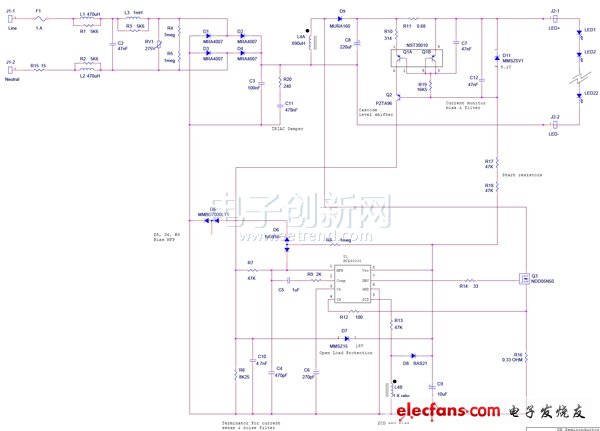
Figure 2: NCL30000 non-isolated buck-boost topology circuit diagram
As shown in Figure 2, in the NCL30000 non-isolated buck-boost topology application, the average LED current is stabilized, which can stabilize line voltage changes and load changes; LED open and short circuit protection can be achieved; if the FET is shorted, the LED remains Safety.
The NCL30000 buck-boost topology works by:
Direct sensing of LED current provides true average mode feedback. The tight current can be maintained over a wide LED voltage range; the sense resistor (R9) has a low resistance value that maximizes energy efficiency; the matched transistor pair (Q1) produces a current proportional to the LED current.
The gradation level shifting transistor (Q2) couples the proportional current to the low side controller; the optocoupler is omitted; the second grading transistor (Q5) is used for the "high input + output" voltage scheme.
• Termination resistor (R14) converts the proportional current into a voltage; uses the voltage as a feedback signal to the controller; turns off the feedback loop at the average LED current.
Low loop bandwidth provides high power factor.
3) T8 lamp LED driver demo board based on NCL30000
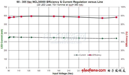
ON Semiconductor offers a high PF demo board for the NCL30000 T8 tube LED driver to replace common linear fluorescent tubes. The 25 W design example has a voltage of 72 V at 350 mA, a main supply voltage range of more than 88%, a typical power factor of more than 0.96, and a size of 18 mm x 200 mm (total height of 19 mm).

Figure 3: Non-isolated buck-boost T8 lamp driver demo board based on NCL30000
The demo board has many features: the controller uses the AC rectification loop voltage as a reference to reduce system noise; the LED uses AC rectified voltage as a reference to reduce the generated EMI; directly senses the LED current to achieve true average mode control; Maintains tight regulation over the LED voltage range; constant on-time provides high power factor and low total harmonic distortion; uses bias winding to provide open load protection; thermal reverse, with automatic recovery; monitors LED current for short-circuit protection; Measure FET current for fault protection. The design requirements for the 25 W T8 lamp LED driver design include: input voltage range of 90 to 305 Vac; 350 mA constant current for the LED; LED string maximum voltage of 71.4 V; LED string minimum voltage of 55 V; minimum AC main The switching frequency is 70 kHz at the peak of the voltage; the energy efficiency is approximately 90%.

Figure 4: NCL30000 Buck-Boost Non-Isolated LED Driver Demonstration Board Performance Test Results
4) TRIAC dimmable high power factor GU10 LED driver solution based on NCL30000
Make some necessary modifications to the above scheme, and also cooperate with TRIAC dimming. Modifications include: adding more turns to the bias leveling, adding a bias regulator for wide-range dimming, an optional accelerated dimming circuit to optimize the dimming response, and optimizing the EMI filter to accommodate TRIAC turn-on The large step voltage and so on. The power supply specification summary of the modified scheme includes: input voltage 100 to 130 Vac; output of 3 LEDs is 470 mA; rated output power is about 4.7W; non-isolated design TRIAC dimming; power factor correction 0.85; 100 to 130 Vac Energy efficiency is 82%.
Second, LV5026MD/29MC series non-isolated buck LED driver solution
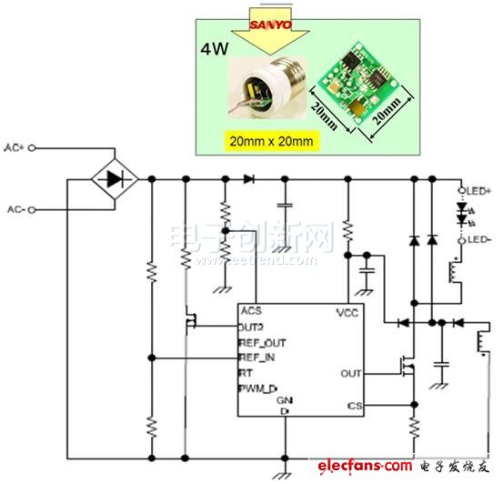
In addition to the NCL30000, customers can also use the LV5026MD/29MC series of non-isolated buck LED drivers from ON Semiconductor's member company Sanyo Semiconductor, and select the appropriate product according to the actual dimming requirements. For example, if you need to support TRIAC dimming, PWM dimming, and analog dimming, you should choose LV5026M; if you only need to support PWM and analog dimming, you can choose LV5029MC. Take the non-isolated dimmable high power factor LED driver LV5026MD as an example, it can drive high-power FET circuit, adopt step control mode, with frequency oscillation, external adjustment of reference voltage, compatible digital dimming and analog dimming, built-in Soft start, over current protection, over temperature protection, over voltage protection circuit and other characteristics. The circuit diagram is shown in Figure 6.

Figure 6: Non-isolated buck LED driver with LV5026MD
When using the LED lighting driver circuit of the LV5026MD, changing the circuit configuration can improve the power factor. Corresponding methods include: reducing the AC voltage smoothing capacitor to increase the conduction angle of the AC current; controlling the current in the power FET to be proportional to the input AC voltage.
to sum up
Both the NCL30000 and LV5026MD support isolated and non-isolated topologies for higher energy efficiency, tight LED steady current over mains input voltage and LED load range, and high power factor and low THD for optimized cuts Phase dimmer application. ON Semiconductor's wide range of LED driver solutions, with associated tools and support, enable a compact design for different low- and medium-power LED lighting applications while helping customers accelerate time to market.
ZGAR AZ Bingo Vape
ZGAR electronic cigarette uses high-tech R&D, food grade disposable pod device and high-quality raw material. All package designs are Original IP. Our designer team is from Hong Kong. We have very high requirements for product quality, flavors taste and packaging design. The E-liquid is imported, materials are food grade, and assembly plant is medical-grade dust-free workshops.
Our products include disposable e-cigarettes, rechargeable e-cigarettes, rechargreable disposable vape pen, and various of flavors of cigarette cartridges. From 600puffs to 5000puffs, ZGAR bar Disposable offer high-tech R&D, E-cigarette improves battery capacity, We offer various of flavors and support customization. And printing designs can be customized. We have our own professional team and competitive quotations for any OEM or ODM works.
We supply OEM rechargeable disposable vape pen,OEM disposable electronic cigarette,ODM disposable vape pen,ODM disposable electronic cigarette,OEM/ODM vape pen e-cigarette,OEM/ODM atomizer device.


ZGAR AZ Bingo Vape Disposable Vapes,ZGAR AZ Bingo Vape disposable electronic cigarette, ZGAR bingo vape pen atomizer ,ZGAR AZ Bingo Vape E-cig,AZ Bingo Vape disposable electronic cigarette,disposable vape,zgar bingo box
Zgar International (M) SDN BHD , https://www.szvape-pods.com