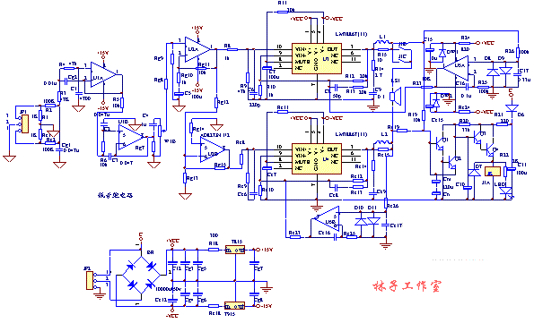
LM3886TF is a new type of high-power audio amplifier integrated circuit launched by the American NS company. The TF behind it is a fully insulated package. Compared with the LM1875T, it has a larger power and a continuous undistorted average of up to 68W at the rated operating voltage The power also has a relatively complete overvoltage, overcurrent and overheating protection function. The most valuable thing is that it has the function of automatically resisting the current impact when switching on and off, so that the speaker can work safely. The excellent performance of LM3886 makes it widely used in audio production in recent years. Many finished power amplifiers have direct application. It acts as a post-stage amplifier or uses it as a subwoofer amplifier circuit. The new high-fidelity audio power amplifier integrated circuit LM3886TF introduced by the American NS company (National Semiconductor Corporation) is used for power amplification, and the operational amplifier NE5532 or AD827 is used for pre-linear amplification and tone amplification. Its characteristics are: large output power (continuous output power 68W), low distortion (total distortion plus noise <0? 03%), protection functions (including overvoltage protection, overheat protection, current limit, temperature limit, switching power supply Speaker impact protection, noise suppression function) complete, few peripheral components, easy production and debugging, stable and reliable work. Because it is simple and suitable for making power amplifying circuits, it is especially suitable for making for fans and electronics enthusiasts.
The electrical parameters of LM3886TF are as follows:
The LM3886 can achieve a continuous average power of 68W at VCC = VEE = 28V and a load of 4 ohms, and an average power of 50W at VCC = VEE = 35V and a load of 8 ohms. It has a wide power supply voltage range VCC + VEE of 20V-94V;
Total harmonic distortion + noise: 60W 20Hz
Total static current: 50mA
Input bias current: 0.2uA
Gain bandwidth product: 8 MHZ
When talking about the sound quality of the power amplifier, the selection of components and the design of the circuit are very important, but there is also a very important thing is the design of the circuit board, the PCB wiring is unreasonable, the best circuit and the most enthusiastic components To no avail, for audio enthusiasts, AC noise and crosstalk of the sound channel are unacceptable. Before designing the first LM3886 power amplifier introduced by this site, the author has consulted and studied some domestic and foreign Audio amplifier circuit board, the simplest source of information is the PCB diagram of the recommended application circuit of some well-known semiconductor manufacturers, trying to achieve the maximum volume of the amplifier board, close the ear to the speaker, there is no effect of exchange hum, and the sound Crosstalk between channels is minimized.
The circuit adopts the integrated design of the front and back stages, the width of the large current part such as the power supply and the output circuit is widened, and the pad is reserved to thicken the solder to reduce the resistance of copper and platinum. The arrangement of the components is more reasonable than the previous model And compact, considering the safety of the back-end speakers, a relatively stable and reliable speaker protection function is added and a better quality relay is used as the Japanese OMRON RELAY. It should be said that the now completed LM3886 power amplifier board is a board with perfect functions and reasonable wiring. As long as the components are selected properly, it will be used to modify the writer's audio. I believe it will achieve satisfactory results. Reasonable grounding is required for wiring, independent front and rear wiring is implemented, after the grounding of the left and right channel amplifier ICs is separated, star grounding, the board is designed to be combined with the front and back stages, but the wiring has been fully considered before and after the wiring Separation, careful fans can observe that the front stage of the PCB board and the back stage of the high-current power amplifier have been separated by several separate ground wires, so basically the phenomenon of electromagnetic dry winding is considered to be minimized. This can be verified in the audition. So as to maximize the excellent performance of LM3886.
Audition:
After assembling the model, after carefully checking the circuit for correctness, connect the connectors of the power supply, signal cable and speaker (note that its polarity is not wrong). The equipment is ordinary products, the sound source is Yushchenko VCD, and the speaker is self-made. After music is turned on, turn up the volume potentiometer and use your ears to close to the speaker. As a result, there is no hum, and the noise (the noise of the integrated circuit itself) is extremely small, and you ca n’t hear it at a distance. This shows that the wiring of this circuit reaches the design. Reasonable, the high current rear stage and the front stage are separated from the wiring and the point grounding measures, effectively reducing the front and rear stage crosstalk, the next exciting time is up, playing music, it feels refreshing, and the previous NE5532 Like the TL082, the superior performance of the high-speed op amp AD827 and the advantages of the LM3886 are fully exerted. The vocal lip and tooth breath are clear and audible, the air feel is very realistic, and the extension of high and low frequencies is better than NE5532. Personally think This is because the conversion rate of the two integrated blocks is very high, and the benefits of combining the two are naturally needless to say.

Follow WeChat

Download Audiophile APP

Follow the audiophile class
related suggestion
As I deepened my understanding of op amps, I realized that the emergence of these problems is related to the phase ...

With the help of Multisim 10's simulation platform, this article uses Multisim simulation to analyze the resistance-capacitance coupled negative feedback amplifier circuit to study ...
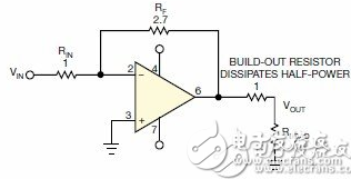
People often use series termination for op amps to match the impedance of the load. But this practical method will produce 3dB output power loss on the termination resistance ...
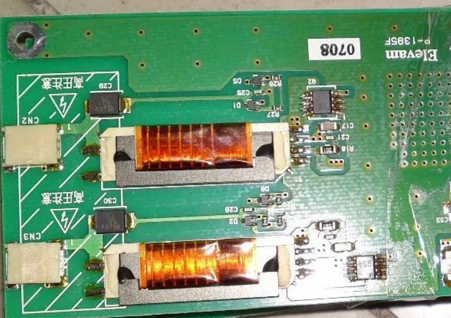
1. Black screen immediately after instant light-up This problem is mainly caused by the feedback circuit of the high-voltage board.
The feedback circuit is widely used in various electronic circuits.Feedback is to feedback part or all of the output signal (voltage or current) of the amplifier to ...
When we design the power supply, the commonly used isolated feedback is the optocoupler + TL431, which is also a hot and difficult point about its adjustment, ...
The so-called feedback means that part or all of the output (voltage or current signal) of the amplifier circuit is returned to the output through a certain method (component or network) ...
The feedback circuit is to recover part or all of the output signal (voltage or current) of the amplifier to the amplifier input and compare it with the input signal (addition or ...
Finding these details and saving the circuit is the same for many people. After completing a project, many of our engineers found that most of the entire project time was spent on "...
The amplification part of the circuit is the basic circuit composed of transistors or operational amplifiers. The feedback is to send back part or all of the signal at the output of the amplifier circuit ...

The signal transmission of the amplifier is transmitted from the input of the amplifier to the output of the amplifier, but the feedback process is different. It is taken from the output of the amplifier ...

The design of analog circuits is the most troublesome, but also the most fatal part of design for engineers! It summarizes the issues that should be noted in the design of analog circuits, ...

The level control circuit is mainly completed by a 32.768KHz crystal oscillator. This circuit generates an oscillation signal by the self-excited oscillation of the crystal oscillator. The signal frequency ...

The schematic diagram of the voltage regulator loop circuit is as follows: 1. Feedback circuit schematic diagram: 2. Working principle: When the output U0 increases, the sampling resistor R7 ...

Sampling of LED string current can be realized by LED string current feedback control circuit. The proportional relationship between the sampled output value and the string current is shown in the equation ...

The power of the PC switching power supply must be able to meet the needs of the whole machine and leave a certain margin. At present, PC is developing in the direction of "green" energy saving and environmental protection, its ...

Electronic enthusiasts provide you with a typical LLC feedback circuit, there are other related resources on this site, I hope to help you!

The optimization design of the flyback converter feedback circuit based on TOPSwitch introduces the flyback converter formed by TOPSwitch ...
Voice filter circuit made by lm387

Design the output detection feedback circuit We always have some inductive loads that need to detect the voltage, we always ...
With a typical feedback circuit with optocoupler primary / secondary isolation, the output voltage overshoot is a common problem during startup
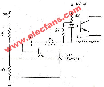
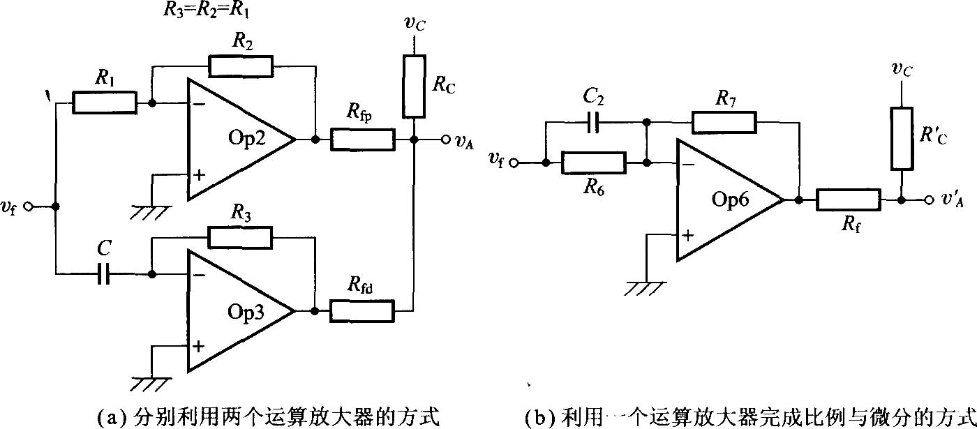
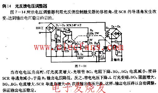
Circuit diagram of optical feedback voltage regulator
I believe the majority of enthusiasts ...
anti...
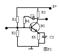
Feedback circuit in electronic circuit & nbs ...
![[Photo] Feedback circuit in electronic circuit](http://i.bosscdn.com/blog/20/06/41/5225849883.gif)
