2, slip motor principle introduction Because the following content, the use of electromagnetic speed control asynchronous motor, commonly known as slip motor, therefore, it is necessary to make a simple introduction to the principle of slip motor. The electromagnetic speed regulating asynchronous motor is composed of three parts: a common squirrel cage asynchronous motor, an electromagnetic slip clutch and an electric control device. The asynchronous motor is used as a prime mover, and when it rotates, the armature of the clutch is rotated together, and the electric control device is a device for providing the excitation current of the slip coil excitation coil.
1 is a schematic structural view of an electromagnetic slip clutch, including an armature, a magnetic pole and an exciting coil. The armature is a cylindrical structure made of cast steel, which is connected with the rotating shaft of the squirrel cage asynchronous motor, commonly known as the active part; the magnetic pole is formed into a claw-shaped structure and is mounted on the load shaft, commonly called the driven part. The active part and the driven part have no mechanical connection. When the exciting coil passes a current, a magnetic field is generated, and the claw-shaped structure forms a plurality of pairs of magnetic poles. At this time, if the armature is dragged and rotated by the squirrel cage asynchronous motor, it cuts the magnetic field interaction and generates torque, so that the magnetic pole of the driven portion rotates together with the active portion armature, and the former rotates lower than the latter. Because the armature can cut the magnetic lines of force only when there is relative movement between the armature and the magnetic field. The principle that the magnetic pole rotates with the armature is not fundamentally different from the principle of the rotating magnetic field of the asynchronous motor with the stator winding. The difference is that the rotating magnetic field of the asynchronous motor is generated by the three-phase alternating current in the stator winding, and the electromagnetic slip clutch The magnetic field is generated by the direct current in the exciting coil and acts as a rotating magnetic field due to the rotation of the armature.
Figure 1 Schematic diagram of the basic structure of the electromagnetic slip clutch When the machine is running stably, the load torque is equal to the electromagnetic torque of the clutch. When the load is constant, the magnitude of the excitation current determines the speed of the driven part. The higher the excitation current, the higher the rotation speed. Conversely, the smaller the excitation current, the lower the rotation speed. According to this characteristic, the rotational speed and torque of the driven portion can be easily adjusted by the electric control circuit.
2, single slip motor blocking method This method is to directly use a single slip motor, the slip motor spindle output (shown in Figure 1), through the mechanical and machine frame hard connection, at this time, the output spindle speed has been Zero. The magnitude of the field current and the magnitude of the output torque are adjusted by applying a DC voltage to the field coil to adjust the magnitude of the load, as shown in FIG.

Figure 2 Schematic diagram of single slip motor blocking method This method requires the user to prepare a DC adjustable voltage source of 0~60~90V/2~8A (maximum). If there is no suitable power supply, it can be realized by voltage regulator plus rectification filter circuit, as shown in Figure 3. In addition, since the speed governor is generally attached when the slip motor is purchased, it can be realized by canceling the voltage closed-loop control portion of the original slip motor governor into a single-phase SCR voltage regulating circuit. However, the disadvantage of this method is that the voltage output is non-linear. In the initial stage, the output voltage changes slowly and the loading is slow. At high output voltages, the output voltage changes rapidly and the load adjustment is difficult.

Figure 3 DC excitation voltage generation circuit - voltage regulation rectifier circuit diagram The advantage of this method is simple, low cost, suitable for high-speed loading test occasions of small and medium power inverters. Since rapid loading and unloading cannot be achieved by excitation, dynamic performance testing cannot be achieved, and performance testing of the power generation state cannot be achieved. In addition, due to the low speed, the slip motor slip head has a relatively low running speed and cannot achieve low speed loading.
3, two asynchronous motors through the slip motor tow method This method uses a slip motor and another asynchronous motor coaxial connection, two motors can be driven by two inverters, as shown in Figure 4. .
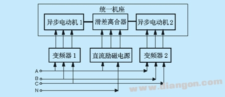
Fig. 4 Schematic diagram of two asynchronous motors passing the slip motor. This method can adjust the load by loading DC voltage on the excitation coil, and adjust the load by adjusting the relative speed of the two motors. That is, the loading of the reverse electric operation can be realized, and the loading of the in-phase power generation operation can also be realized. Due to the relative speed, zero speed or low speed loading can be achieved compared to the above three single slip motor solutions. The disadvantage is that the sliding motor is loaded with electromagnetic induction and slip, the loading response is slow, and fast loading is not possible, so it can not meet the high-precision and fast performance test.
4, two AC motor tow method This method is to use two coaxial motors of the same power coaxial connection, two motors are driven by two inverters, as shown in Figure 5. One of the motors is driven by a test inverter and the other is driven by a closed-loop vector control inverter with precise torque control, such as Emerson's TD3000 series. By changing the magnitude and direction of the torque, the load of the motor under test can be realized, and the performance of the test inverter can be verified.
Figure 5 Two AC motor pairing method This method can realize the loading of the reverse electric operation, and can also realize the loading of the in-phase power generation operation. Thanks to the closed-loop torque control, high-torque, high-precision loading of zero speed, low speed and high speed can be achieved. Since the motor connection is mechanically hard-connected, the torque response of the asynchronous motor is faster than that of the slip motor, and the load response speed is faster, which can meet the test requirements of most occasions, but it is not completely accurate for high-precision and fast performance test. Satisfy.
5, AC and DC unit tow method This method uses a DC motor and another asynchronous motor coaxial connection, as shown in Figure 6. The asynchronous AC motor is driven by the inverter under test, and the DC motor is driven by a DC governor that can operate in four quadrants. The DC motor can verify the performance of the test inverter by accurately controlling the torque and changing the magnitude and direction of the test torque to achieve any change in the load of the motor under test.
The method can realize the loading of the reverse electric operation, and can also realize the loading of the in-phase power generation operation. Due to the closed-loop torque control of the DC motor, high torque and high precision loading of zero speed, low speed and high speed can be realized. Since the motor connection is mechanically hard-connected, the DC motor has a fast torque response and a fast loading response speed, which basically satisfies the testing requirements of most occasions, and is currently the most ideal test method.
6. Conclusion By analyzing the load test methods of the above four inverters, it can be seen that each method has advantages and disadvantages. As for what kind of test plan the user needs to choose, different test plans need to be selected according to the purpose of the test. It should be emphasized that if the user adds a torque Sensor in the middle of the unit described in Sections 4, 5 and 6, the output torque of the motor can be accurately known. The author's purpose in writing this article is to answer the questions related to load commissioning that many customers and peers often consult. It has certain reference for inverter production, design manufacturers, inverter users and so on.
Optoelectronic Information Series
Photoelectric information series laboratory related equipment
Optoelectronic Information Product,Optical Bench Experiments Physics,Optical Devices Physics,Optical Physics Properties
Yuheng Optics Co., Ltd.(Changchun) , https://www.yhenoptics.com