A common application of simple RF data transmission is the remote keyless entry (RKE) system that is common in most cars today. In these systems, it can control the opening and closing of the door, open the suitcase, and prevent theft. In the future, RKE may also be used to locate and start vehicles with distance.
The work of the RKE system is intuitive. It consists of a transmitter similar to a keychain (usually one per person) and a receiver on the car. The operating frequency is generally 300MHz to 450MHz, but some new systems in Europe consider using the 868MHz allocated in the ISM band. Communication is unidirectional, that is, data only goes from the transmitter to the receiver. The most important reasons for trying this structure are the low price and the longest life of the battery in the transmitter.
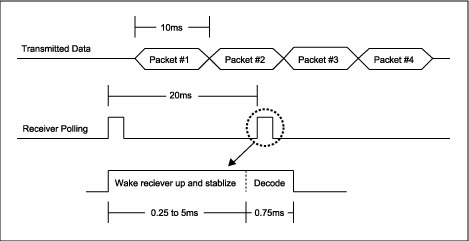
When starting work, the user presses the button on the key fob to wake up the internal MCU to send a stream of data into the RF transmitter. The data stream includes leading data, actual commands (such as locking the door), and a channel code for vehicle identification to ensure Your key will not open other cars and some check digits. Figure 1.

Figure 1. In the remote keyless access control system, pressing the button on the launch button initiates the transmission of a short data stream.
The complete data packet (64 to 128 bits) is usually sent at a rate of 2.4kHz to 20kHz, and the RF modulation method uses keyed amplitude shift (ASK) or keyed switch (OOK, that is, ASK with modulation levels of 0% and 100%) . These modulation methods lower the price and extend the battery life in the key fob.
Low price and long battery life are very important in this application. When you consider the quantity (tens of millions) used by this system, a low price is necessary. In addition, the longest battery life is important for both the transmitter and receiver.
For the keychain transmitter, the long battery life means that users can replace the battery less. The ideal transmitter battery should last as long as the car has been used. There are already such batteries, but you may not want to carry a large keychain in your pocket or bag. A small keychain is more convenient, but if every two It is inconvenient to change the battery every month. Therefore, the battery life of current products is generally 2 to 5 years when the size is appropriate.
The battery life of the receiver is equally important. The receiver must always be on, and the user may transmit commands at any time. The RKE receiver is powered by the car's battery (that is, the battery used to start the car). If the power consumption of the receiver is too high, the battery may not have enough power to start the car.
On the surface, this worry is stupid, the car battery is very large, and the typical power consumption of the receiver is only 1mA to 5mA. Such a small current in daily use does not matter at all, but if you park your car at the airport for several weeks or longer, the situation is different.
The car manufacturer uses this to determine the capacity of the battery. For a certain RKE system, the battery size (capacity) is directly proportional to the product of the receiver's power consumption and continuous operating time. Therefore, they will warn you in advance whether the car has enough power for more than 30 days. Now back to the topic of this article-how does the fast start of the oscillator in the superheterodyne receiver affect the battery life?
To simplify the calculation, we used some intermediate values. The data packet and transmission rate have been discussed previously. Assume that the data packet is 100 bits and the data rate is 10 kHz (0.1 ms per bit). Then it takes 10ms to send 100 bits. In order to save power, we divide the work of the receiver into time slices and only let it turn on for a short time-just enough to determine whether there is a valid transmission. Turn-on time usually accounts for about 10% of the time.
Since the receiver works in time-sharing, we must provide additional transmissions to enable the receiver to detect the required commands. The keychain is usually sent more than three times. If you send 4 times in total, the total sending time is 4x10ms, 40ms. For the receiver to act, it must decode at least one of the 100 bits (10ms) sent.
In order to get at least a complete transmission, the receiver must work round-robin to see if there is valid data (of course, the receiver can be on all the time, but this consumes more power), the given 40ms data packet will not be repeated, so we It must be polled frequently enough to get one full 10ms transmission. Thus, the maximum polling time interval is 30ms.
The interval should not be too large, so you may miss receiving commands. The system timing may be interrupted, or interference or other noise may damage the data. Be conservative and estimate that the system should be able to receive at least two complete transmissions. So we set the time interval to 20ms. The receiver wakes up every 20ms to decode the data stream, and decodes if there is data, otherwise it goes to sleep and waits until the next 20ms.
In order to determine whether it is valid data, the receiver needs at least 7 to 8 bits of data, that is, 0.75ms time to decode the information, in order to determine whether the transmitter sent data of a certain frequency and format of interest. Therefore, the receiver must wake up about 0.75ms every 20ms. Unfortunately, only a very perfect receiver can achieve this level.
It also takes time for the receiver to wake up. Most amplifiers in the receiver can be stabilized in a short time, but the oscillator cannot, and the piezoelectric crystal is an electromagnetic component. It takes time to start and takes longer. In order to stabilize at the required frequency.
Note that many receiver indicators are ambiguous at this point. The important parameter is the time from when the receiver is turned on to when the oscillator frequency in a given range is obtained (ie, stable). Other parameters, such as the IF output time, will be misleading. When the oscillator starts to oscillate, the IF will be output, but the frequency of the receiver is not locked to the frequency of the transmitter. This situation is like a radio tuned to 90MHz. But actually received 92MHz, of course, the radio is working, but it did not receive what you want.
Generally, the superheterodyne receiver can start and stabilize within 2ms to 5ms. Assuming that it is 2.25ms in our discussion, it also needs 0.75ms for data decoding, so that every 20ms time needs 3ms to detect the data transmitted by the key fob (Figure 2). The MAX1470 superheterodyne receiver is different. It has a built-in fast-start oscillator, which reduces the start-up time by maintaining the oscillation in the crystal. Therefore, the start-up time is reduced from 2.25ms to 0.25ms. 0.25ms plus 0.75ms data decoding time, we only need 1ms time to detect the transmitted data, MAX1470 only needs 1/3 of the original time to complete the same detection function, saving energy.

Figure 2. In order to monitor the transmission of the transmission buckle, the RKE receiver must allocate time to wake up, stabilize, and then decode.
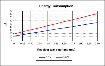
Most high-performance superheterodyne receivers (that is, with high sensitivity) consume 5mA when operating at 5V. The MAX1470 has the best sensitivity, and consumes 5mA at 3.3V. Low-voltage operation is very power-saving: general receivers It needs 25mW; MAX1470 only needs 16.5mW. Considering the working time, every 20ms time slice, the general superheterodyne receiver needs 25mW 3ms = 75µJ; MAX1470 only needs 16.5mW
1ms = 16.5µJ (Figure 3). It can be seen that the power-saving fast wake-up receiver can extend the battery life by 4 to 5 times.

Figure 3. Shorter wake-up time also saves energy, just like lowering the supply voltage.
Therefore, for a given battery life, we can use a smaller battery while saving costs. On the other hand, in the case of consuming the same power, it can be detected more frequently, so that the transmitter can use a smaller size battery. The reason is that the size of the car battery is mainly determined by the starting current and energy storage capacity. Reducing the size does not necessarily bring price advantages, but reducing the battery of the transmitter can bring many advantages, especially in new In the tire pressure monitoring (TPM) system.
The TPM transmitter is basically a launch buckle placed on the valve stem in the tire. It measures the tire pressure and temperature and sends a data packet, just like a wireless key buckle. But the information is sent very frequently (compared to the key resend), because you have to immediately detect the air pressure problem. To detect slow air leaks, the system needs to monitor each tire while the car is parked.
Note: Do not place a large battery on the valve stem, it will affect the wheel balance. However, the battery of the receiver cannot be easily replaced, so it should be much longer than the battery on the transmitter buckle. This shows that a low-power transmission system is a basic requirement for TPM. Although designers of RKE transmitters will naturally consider low power consumption, system engineers know that improving receiver performance will also increase power consumption. Therefore, both low power consumption and receiver performance must be improved. The oscillator's superheterodyne RKE receiver is a better choice.
Ceramic capacitor (ceramic capacitor);Ceramic condenser) is also known as porcelain capacitor or monolithic capacitors.As the name implies, ceramic dielectric vessel is a ceramic capacitor with dielectric material.According to different ceramic materials, this kind of capacitor can be divided into low-frequency porcelain dielectric vessel with capacity of 1-300 pF and high-frequency porcelain dielectric vessel with capacity of 300-22 000 pF.According to the structure type classification, can be divided into picture capacitor, tubular capacitor, rectangular capacitor, chip capacitor, piercing capacitor and so on.
Ceramic Capacitor,White Ceramic Capacitor,Smd Ceramic Capacitor,Multilayer Chip Ceramic Capacitor
YANGZHOU POSITIONING TECH CO., LTD. , https://www.pst-thyristor.com