One or three connection methods
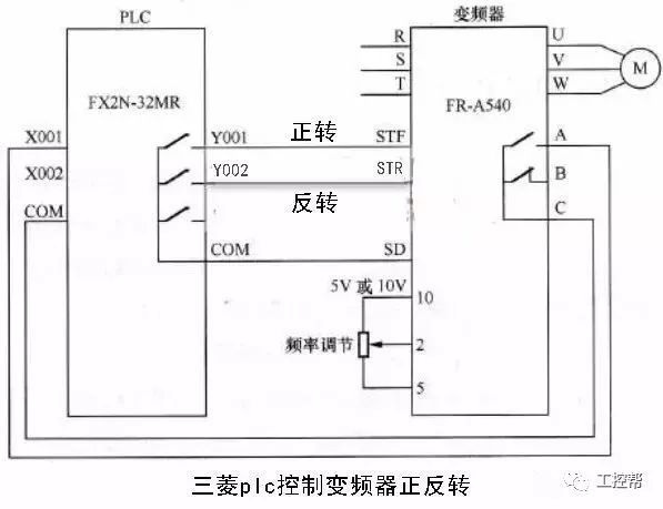
1, the switch quantity onlineThe inverter is controlled by the switching output of the PLC. The switching output of the PLC can generally be directly connected to the digital input of the inverter. This type of control has simple wiring and strong anti-interference ability. The switching output of the PLC can control the start/stop, forward/reverse, jog, multi-speed and addition and subtraction time of the inverter, which can realize more complicated control requirements, but only has step-level speed regulation.
The inverter is controlled by the analog output module of the PLC. The analog output module of PLC outputs 0~10V voltage signal or 4~20mA current signal as the analog input signal of the inverter to control the output frequency of the inverter.
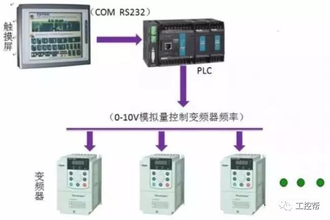
This control mode is simple to wire, but it is necessary to select the PLC output module that matches the input impedance of the inverter, and the analog output module of the PLC is more expensive. In addition, the voltage divider is required to adapt the inverter to the voltage signal range of the PLC. Be careful to separate the wiring when connecting.
3, communication onlineThe connection between the PLC and the inverter through the RS-485 communication interface. A large number of inverters have an RS-485 serial interface (some also provide RS-232C interface), with a two-wire connection, and its design standards are suitable for industrial environment applications.
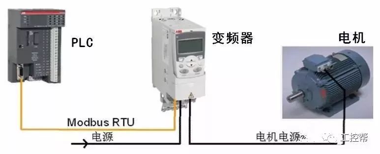
Up to 30 inverters can be connected to a single RS-485 link, and the inverters that need to communicate can be found according to the address of each inverter or using broadcast information. A master controller (master station) is required in the link, and each inverter is a slave control object (slave).
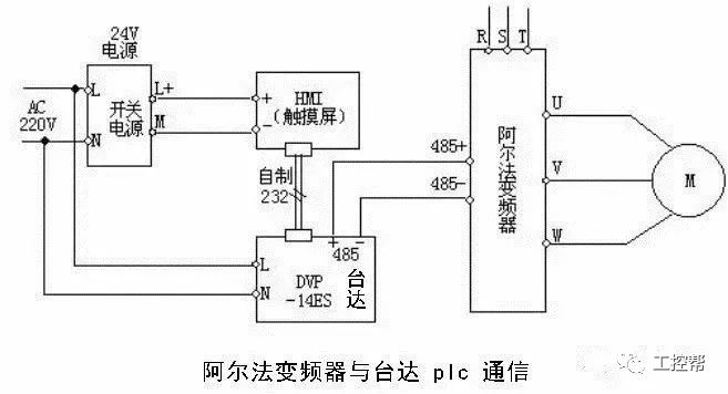
Advantages of using serial communication
1 greatly reduces the number of wiring.
2 Change the control function without rewiring.
3 The parameters of the inverter can be set and modified through the serial interface.
4 The characteristics of the inverter can be continuously monitored and controlled.
Second online considerations
1. Switching quantity signal precautionsThe inverter usually uses a relay contact or a component with a relay contact switch characteristic (such as a transistor) to connect to the PLC to obtain an operational status command, as shown in Figures 1(A) and (B).
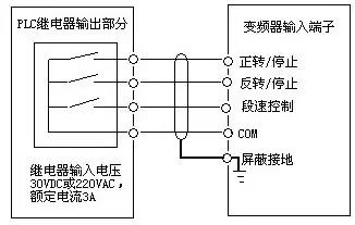
Figure 1 A relay type PLC output and inverter connection operation mode
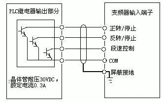
Figure 1 B Operation mode of transistor type PLC output connected to the inverter
When a relay contact is used, it often causes malfunction due to poor contact; when using a transistor to connect, it is necessary to consider the voltage and current capacity of the transistor itself to ensure the reliability of the system.
When designing the input signal circuit of the inverter, it should also be noted that when the input signal circuit is not connected properly, the inverter may malfunction. For example, when the input signal circuit uses an inductive load such as a relay, the inrush current generated by the relay opening and closing may cause damage or failure of the internal components of the inverter, which may cause the inverter to malfunction. Therefore, this situation should be avoided as much as possible. . Figure 2 and Figure 3 show examples of correct and incorrect wiring.
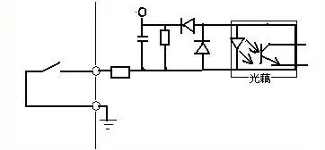
Figure 2 Inverter input signal connection method
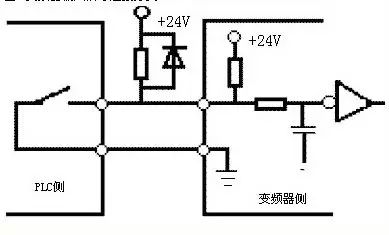
Figure 3 Error connection of the inverter input signal
Crosstalk between the external power supply and the drive control power supply (DC24V) sometimes occurs when the input switch signal enters the drive. The correct connection is to use the PLC power supply to connect the collector of the external transistor to the PLC via a diode. As shown in Figure 4.
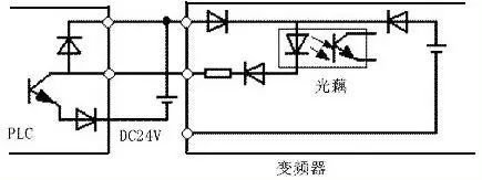
Figure 4: Anti-jamming connection method for input signals
2, analog signal considerationsThe analog input is externally given through the terminal, and is usually input through a voltage signal of 0 to 10V/5V or a current signal of 0/4 to 20 mA. Since the interface circuit varies depending on the input signal, the output module of the PLC must be selected according to the input impedance of the inverter.
When the voltage signal range of the inverter and PLC is different, for example, the input signal of the inverter is 0~10V, and the output voltage signal range of the PLC is 0~5V; or the output signal voltage range of one side of the PLC is 0~ 10V and the input voltage signal range of the inverter is 0~5V. Due to the limitation of the voltage and current of the inverter and the transistor, it is necessary to connect the resistor in series and series to limit the current or divide. Part of the voltage to ensure that the corresponding capacity of the PLC and the inverter is not exceeded when opening and closing. In addition, when connecting the line, you should also pay attention to separating the control circuit from the main circuit. The control circuit is preferably shielded to ensure that the noise on the side of the main circuit is not transmitted to the control circuit.
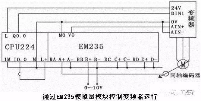
In either case, it should be noted that the input impedance of the PLC side should be such that the voltage and current in the circuit do not exceed the circuit's allowable value to ensure system reliability and reduce errors. In addition, when using PLC for sequential control, it takes time to perform data processing, and the order of arrangement and the use of instructions are different when the program is written. This will cause the system to have a certain time delay during operation, so in the case of more precise control. The above factors should be considered.
Since the inverter will generate strong electromagnetic interference during operation, in order to ensure that the PLC does not malfunction due to noise generated by the main circuit breaker and switching device of the inverter, the following points should be noted when connecting the inverter to the PLC. :
(1) The PLC itself should be grounded according to the specified wiring standards and grounding conditions, and care should be taken to avoid using the common grounding wire with the inverter, and to make the two separate as much as possible when grounding.
(2) When the power supply condition is not good, the noise filter, the reactor and the device for reducing noise should be connected to the power supply module of the PLC and the power supply line of the input/output module. In addition, if necessary, The corresponding measures should also be taken on the input side of the inverter.
(3) When installing the inverter and PLC in the same control cabinet, the wires related to the inverter and the wires related to the PLC should be separated as much as possible.
(4) The level of progressive noise interference is achieved by using shielded wires and twisted pairs.
12.8V150Ah Lithium Iron Phosphate Battery
FEATURES & BENEFITS
Saintish lithium iron batteries use top quality cells, which are auto grade A LiFePO4 cells with higher energy density, more stable performance . UL approved for the cells inside the battery.
The lithium-ion batteries are perfect for solar system, caravan, RVs, campers, Yacht, off-grid applications and lead aicd replacement.
The Lithium Iron Phosphate Battery provides 3000+ cycles (@100%DoD) and 10 years lifespan. which is 10 times than lead-acid battery. 1/3 of the weight of lead acid, Saintish LiFePO4 Battery weighs only 20.8kgs each pc, but delivers twice power.
Saintish lithium iron phosphate battery has built-in BMS to protect it from overcharge, over-discharge, over current, and short circuit with excellent self-discharge rate. Operating Temperature: Charge: 0°C~45°C; Discharge: -20°C~60°C.
SPECIFICATIONS
| Rated Capacity | 150Ah | Charge Temperature | 0-45℃ |
| Nominal Voltage | 12.8V | Connection Method | Parallel & Series |
| Energy | 1920Wh | Dimensions | 483*170*240mm |
| Cycle Life | >3000@100% DOD | Weight | 20.8KG |
| Maximum Charging Current | 50A | Terminal Torque | 12-15N.m |
| Maximum Continuous Discharging Current | 100A | Enclosure Protection | IP65 |
| Discharging Voltage Range | 8.4-15.2V | Max. Batteries in Series | 4 |
| Charging Voltage Range | 14.4-15.2V | Certifications | CE, UN38.3, MSDS |
| Discharge Temperature | -20-60℃ | Warranty | 5 Years |
LiFePO4 Battery 150Ah, 150Ah Battery, Lithium Phosphate Battery, Lithium Iron Battery
Hangzhou Saintish Technology Co.,Ltd. , https://www.saintishtech.com