The video graphics array display interface is a general-purpose display interface used by the microcomputer system, and is widely used in an intelligent control system as a display terminal of the system. For an image processing system composed of an embedded microprocessor, the VGA display output has the advantages of strong compatibility and rich display content. At the same time, the VGA display interface has the characteristics of simple structure, reliable performance, strong compatibility, and easy timing control. Therefore, the VGA image controller combined with FPGA has broad application prospects in embedded image processing systems.
At present, most computers and external display devices are connected through an analog VGA interface, and the digital display image information generated inside the computer is converted into three primary color signals and rows by the digital/analog converter in the video card. The synchronization signal is transmitted to the display device via a cable.
1 VGA display
The color display of the common VGA interface is generally composed of cRT (cathode ray tube), and the color is composed of R, G, B (red: Red, green: Green, blue: Blue). The display is performed by progressive scanning. That is, when one line is scanned, the next line is scanned until the last line is scanned. The VGA interface provides two types of signals for the display, one is a data signal, and the other is a control signal.
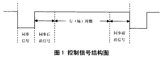
The data signal includes red, green, and blue signals, referred to as RGB signals. The control signals include a horizontal sync signal (HSYNC) and a vertical sync signal (VsYNc). When the different resolutions are output to the display, the frequencies of the horizontal sync signal and the vertical sync signal are also different. However, the horizontal synchronizing signal and the vertical synchronizing signal have the same timing analysis, and all of the four periods of the synchronization signal, the post-synchronization signal, the line synchronizing signal, and the post-synchronization signal are required during scanning. Take the horizontal sync signal as an example, and its structure is shown in Figure 1.

The display principle of the VGA interface is actually equivalent to a dot matrix, which is lit by the controller to illuminate the rows and columns. So the horizontal sync signal is for column pixels, and the vertical sync signal is for row pixels.
Taking the picture size of 800 & TImes; 600 as an example, according to the timing standard of VGA, the refresh frequency of 6hz is selected. The synchronization signal of the horizontal synchronization signal includes 128 column pixels, the synchronization trailing edge signal is 88 column pixels, the synchronization leading edge signal is 40 column pixels, and the screen display portion is 800 column pixels, so a total of 1 28+88+40 is needed. +800=1 056 column pixels. The sync signal of the field sync signal contains 4 line pixels, the sync trailing edge signal contains 23 line pixels, the sync front edge signal contains 1 line pixel, and the screen display part is 600 line pixels, so a total of 4+23+l+ is needed. 600 = 628 line pixels, whereby the liquid crystal display displays an image of 800 & TImes; 600, and the required row and column pixels are 1056 and 628, respectively.
Active harmonic filter module is a new type of power electronic device used to dynamically filter harmonics and compensate for reactive power. They can filter out harmonics in real time to overcome the shortcomings of harmonic suppression and reactive power compensation of traditional filters.
power electronic device,dynamically filter harmonics,compensate for reactive power,Harmonic Filter
Jiangsu Sfere Electric Co., Ltd , https://www.elecnova-global.com