Analog audio is influenced by the outside world and has poor stability. Therefore, digital audio gradually replaced analog audio as the main form of modern audio. The digital audio signal is directly output from the set-top box and is not internally D/A converted, and the digital audio is wirelessly forwarded. D/A conversion is performed at the receiving end, which can avoid the effects of audio cabling and the loss of audio quality on the audio line. This method can effectively reduce the interference inside the set-top box and ensure better sound quality.
The 2.4 GHz digital high-speed radio frequency technology is a relatively mature audio application wireless technology. Its strong anti-interference, transmission distance, and the use of a completely open network protocol. The nRF24 Z1 radio frequency chip operates at 2.4 GHz, communication speeds up to 4 Mbps, actual audio data transmission rate of 1.54 Mbps, and has an S/PDIF digital audio signal interface. The program directly extracts the digital audio S/PDIF signal from the set-top box to ensure a better sound quality; it transmits and receives through the nRF24Z1 wireless RF chip, ensuring the lossless wireless transmission of audio.
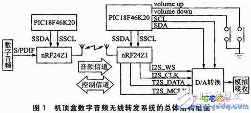
The overall block diagram of the set-top box digital audio wireless relay system is shown in Figure 1. The system consists of three parts: digital audio signal extraction and transmission, digital audio wireless transmission, and digital audio wireless reception. Most set-top boxes have digital audio S/PDIF output interfaces and generally use coaxial output. The radio frequency chip nRF24Z1 can be used to send audio data at the source side, and can also receive audio data at the receiving end. The PIC18 series microcontrollers are used to configure the corresponding registers of the RF chip to realize the digital audio wireless transmission and reception. After being internally processed, the nRF24Z1 chip outputs I2S digital audio signals, which are sent to the digital-analog conversion chip and peripheral circuits for analog reception. At the same time, the use of SCM to control the volume increase or decrease.
The nRF24Z1 is a monolithic CD-quality digital audio chip introduced by NorDIC Corporation. The wireless audio transmission rate is up to 48KspS, 16 bits without any compression. It operates in the globally-available 2.4 GHz band, providing high-performance and highly-integrated solutions at a very low cost; with I2S and S/PDIF digital audio interfaces for direct connection to ADC/DAC, or with digital The audio output device is directly connected. Since all the related functions of audio I/O, RF protocol and RF link management have been embedded in the chip, the chip provides a transparent 1.54 Mbps audio channel without additional processing time.
3 digital audio signal extraction and interface circuitMost set-top boxes have S/PDIF coaxial outputs. For set-top boxes that do not have a S/PDIF direct output interface, S/PDIF fiber/coaxial output interfaces can be added. Different installation methods for different set-top boxes:
1 MPEG-2 decoder chip S/PDIF output pin set-top box, the S / PDIF output signal, and sent to the buffer amplifier and coaxial RCA terminal can output digital S / PDIF signal.
2 For I2S-only MPEG-2 decoder chip, the DATA, BCLK, and LRCK signals of I2S are sent to the PCM/SPDIF conversion chip and output in S/PDIF format, and the conversion circuit is added to realize the S/PDIF signal. extract.
The S/PDIF coaxial transmission signal combines data and clock signals with high frequency and sharp edge characteristics. The coaxial line has a characteristic impedance of 75 Ω, and the output S/PDIF signal voltage is only 0.5 Vpp and cannot be directly connected to a CMOS chip. Therefore, the output S/PDIF signal is level-shifted so that it can be directly input to the S/PDIF input pin of the nRF24Z1 chip. Level conversion circuit shown in Figure 2.
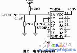
The S/PDIF signal is boosted by the front-end circuit and then amplified to the TTL level by the 74HC04 inverting amplifier. However, the output signal is inverted at this time, so it is passed through another set of inverting ports of the 74HC04. Invert the signal back again. Note that the 74HC04 pins 14 and 7 are connected to +3.3V and ground, respectively, to allow the circuit to work properly; the S/PDIF signal reaches the operating voltage of the nRF24 Z1 and can be used directly.
Wireless Bridge,Wifi Wireless Bridge,Gigabit Wifi Bridge,Long Range Wifi Bridge
Shenzhen MovingComm Technology Co., Ltd. , https://www.movingcommiot.com