This paper analyzes the characteristics of the ZigBee protocol and designs an automatic control system for indoor lighting suitable for smart homes. Analyzed the problems in the existing indoor lighting automatic control system, applied ZigBee technology to the lighting automatic control system, and built a ZigBee wireless network system on the PICDEMZ platform to realize the wireless control of the indoor lighting system and increase the flexibility of the system And practicality.
1 Introduction
With the advancement of science and technology, people's requirements for communication technology are also increasing, and short-range wireless communication technology has also emerged.
Nowadays, various short-range wireless communication technologies are emerging one after another. Among them, Bluetooth, ZigBee, Wi-Fi, WiMAX, wireless USB and UWB are more successful and widely used.
The ZigBee protocol framework is based on the IEEE 802.15.4 standard. The IEEE 802.15.4 standard defines the ZigBee physical layer (PHY) and media access control layer (MAC); the ZigBee Alliance defines the network layer (ZWK), application layer (APL), and security service specifications of the ZigBee protocol. As an emerging low-rate wireless communication technology, ZigBee technology has a variety of low speed, low power consumption, low cost, license-free wireless communication frequency band, short-range communication, short delay, reliable data transmission, and diverse networking methods. Technical characteristics, these characteristics make ZigBee technology suitable for industrial control, smart home, medical care, smart agriculture, consumer electronics and remote control. At present, the Bluetooth technology is complex, the application system costs are high, the power consumption is high, and the battery life is short. In the case where it cannot break through the price bottleneck, ZigBee technology will have a broader application prospect.
According to the requirements of the ZigBee protocol specification, this paper designs a set of indoor lighting automatic control system suitable for smart home network. The system can accurately realize the remote control of indoor lighting devices, and can adjust the opening and closing of electric lamps by monitoring the changes of indoor light to realize intelligent control of lighting, and at the same time improve the reliability and flexibility of the control system.
2. Indoor lighting automatic control system structure based on Microchip ZigBee protocol stack
The indoor lighting automatic control system introduced in this article is a typical application of ZigBee technology in smart home.
The Microchip Stack for ZigBee protocol is defined on the basis of the ZigBee wireless protocol specification, but it does not fully comply with the ZigBee protocol, does not support clusters and point-to-point networks, has no security and access control functions, does not have router functions, nor supports one-to-many binding . Use the Microchip ZigBee protocol stack to design a ZigBee node. The hardware requirements must include at least a PIC18F microcontroller with an SPI serial port, an RF transceiver with the required external components, an antenna, which can be formed by the leads on the PCB. Antenna or monopole antenna.
The system constructs a star network, that is, a master-slave network composed of a coordinator node and several terminal nodes. The first FFD (Full-Function Device) to start as its own PAN coordinator, and choose an identifier different from other PANs in its coverage area as its own PAN identifier. Generally, when there is no other PAN in its work area, the PAN flag is set to 0. The coordinator can allow other FFDs and RFDs (Reduced Function Devices) to join the network. In a star network, the coordinator node and the terminal node can send or receive data with each other, but there is no direct communication between the two terminal nodes. If one terminal node wants to send data to another terminal node, only through coordination The intermediary device is completed.
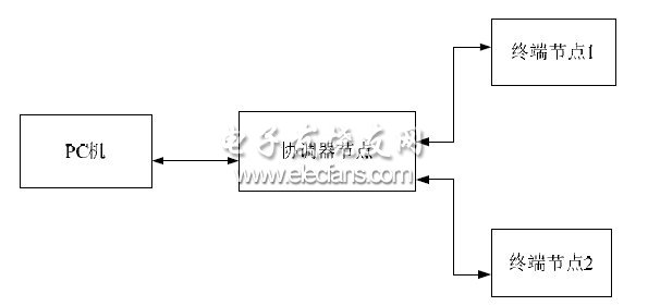
According to the development requirements of the Microchip ZigBee protocol stack, we designed an indoor lighting automatic control system that can be transplanted to the Microchip ZigBee protocol stack. The block diagram of the system is shown in Figure 1.
The coordinator node and all terminal nodes together form the ZigBee wireless communication network. The role of the coordinator node is to establish a network and assign network addresses to the nodes added to the network. It is also responsible for communicating with the host computer through the serial port. Each terminal node is to realize the specific function of switching lights, and The result of the work is fed back to the coordinator node. In addition to monitoring the network working status in real time, the host computer also functions as a home gateway, that is, it can provide various remote intelligent control interfaces to establish a connection between the ZigBee network and the Internet inside the home, so that users can use one Go to a PC on the Internet to control electrical appliances at home.

Figure 1 Schematic diagram of the structure of the lighting control system
3. Hardware design of the system node
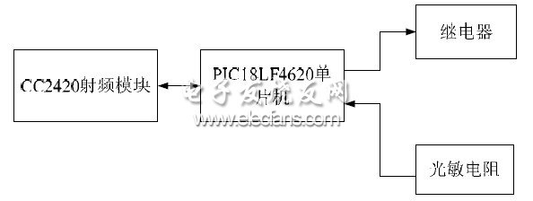
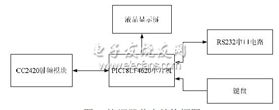
The design uses Microchip's PIC18LF4620 microcontroller as the controller, and the RF transceiver part uses TI's CC2420 RF module. The controller is connected to the RF module through the SPI bus and some discrete control signals. The controller acts as the SPI master device, and the RF module acts as the slave device. The controller implements the IEEE 802.15.4 MAC layer and ZigBee protocol layer, and the RF module CC2420 implements the IEEE 802.15.4 physical layer and some MAC layer functions. Figure 2 is the structural block diagram of the terminal node: Figure 3 is the structural block diagram of the coordinator node:

Figure 2 Block diagram of the terminal node

Our Surface Mount Box could include the CAT5E CAT6 CAT6A RJ45 Connectors
The surface mount box is an ideal for wall box and wire installation, we design many junction box, back mount box, blank mount box, loaded surface mount box.
Mateiral: ABS, PBT UL94V-0
1~8 ports and colors supply for your choice, they are an ideal for low voltage application for your security, data, networking solutions and telecom projects.
CAT5E Surface Mount Box,Surface Mount Box,Adapter Inline Coupler,single port junction surface mount box
NINGBO UONICORE ELECTRONICS CO., LTD , https://www.uonicore.com