(1) A parallel input and output LSI chip, a multi-functional I/O device, can be used as an interface between the CPU bus and peripherals.
(2) There are 24 programmable I/O ports, that is, the 3 groups of 8-bit I/O ports are PA port, PB port and PC port. They can be divided into two groups of 12-bit I/O ports. Group A includes A port and C port (high 4 bits, PC4~PC7). Group B includes B port and C port (low 4 bits, PC0~PC3). . Group A can be set as basic I/O port, flash control (STROBE) I/O flash control type, bidirectional I/O 3 modes; Group B can only be set as basic I/O or flash control type I/O This mode is completely determined by the control word of the control register.
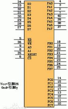
8255 pin and function
RESET: resets the input line. When this input is high, all internal registers (including the control register) are cleared and all I/O ports are set to input mode.
CS: chip select signal line, when this input pin is low, that is / CS = 0, indicating that the chip is selected, allowing the 8255 to communicate with the CPU; / CS = 1, 8255 and CPU can not do data transmission.
RD: Read signal line, when this input pin is a low transition edge, ie /RD generates a low pulse and /CS = 0, allows the 8255 to send data or status information to the CPU via the data bus, ie the CPU reads from the 8255 Get information or data.
WR: Write signal, when this input pin is a low transition edge, that is, /WR generates a low pulse and /CS = 0, allows the CPU to write data or control word to 8255.
D0 ~ D7: Tri-state bidirectional data bus, 8255 and CPU data transfer channel, when the CPU executes input and output instructions, through it to achieve 8-bit data read / write operations, control word and status information is also transmitted through the data bus.
The 8255 has three independent input/output channel ports, operates from a single +5V supply, and can operate in the following three modes.
Mode 0 --- basic input and output mode; Mode 1 --- strobe input / output mode; Mode 2 --- two-way strobe input / output mode;
PA0~PA7: Port A input and output lines, an 8-bit data output latch/buffer, and an 8-bit data input latch. Work in any of three ways;
PB0~PB7: Port B input and output lines, an 8-bit I/O latch, and an 8-bit input/output buffer. Can't work in way two;
PC0 ~ PC7: Port C input and output lines, an 8-bit data output latch/buffer, and an 8-bit data input buffer. Port C can be divided into two 4-bit ports by operating mode settings. Each 4-bit port contains a 4-bit latch that can be used with Port A and Port B as control signal output or status signals. Input port. 'Can't work in way one or two.
A1, A0: Address selection line, used to select 8255's PA port, PB port, PC port and control register.
When A1=0, A0=0, PA port is selected;
When A1 = 0, A0 = 1, PB port is selected;
When A1=1 and A0=0, the PC port is selected;
When A1=1.A0=1, the control register is selected.
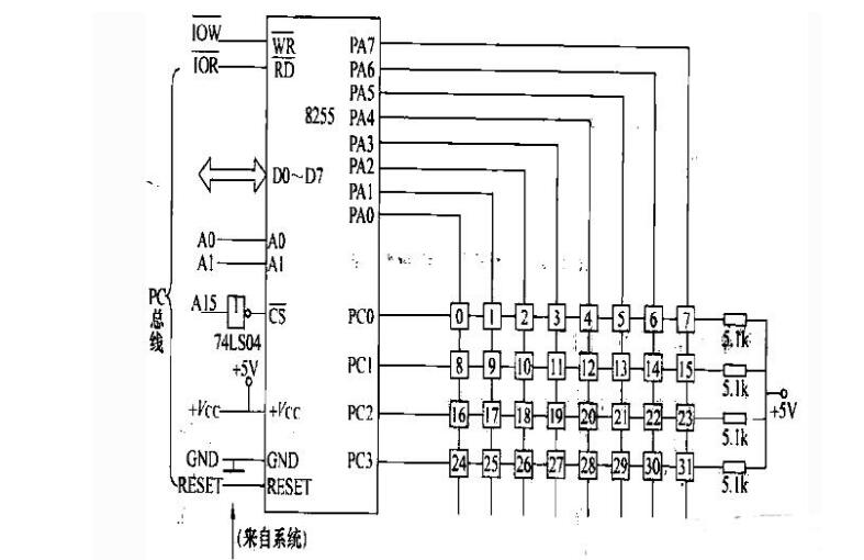
8255 application circuitShown as 8255j port configuration Qi '4X8 matrix keyboard. The 8255's PA port is initialized to the output working mode as a column line. The PC port is used as a row line for the input working mode. A button is connected at the intersection of each row line and the column line, and each button is set. Set a number [key]. According to need, a part of the keys can be defined as function keys, and the other part of the keys can be defined as numeric keys.

Programmable interface 8255A port address is determined by its pin
A1A0=00, on behalf of the A port address
A1A0=01, which represents the B port address
A1A0=10, which represents the C port address
A1A0=11, stands for control word register port address
8255 Port Address CalculationDocument 1:
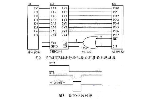
Fig. 2 is the principle circuit that uses 74HC2244 chip to carry on the input interface to expand, Fig. 3 is the time sequence of reading PO mouth. Can be found out by Fig. 3, when P2.7 and RD are low level, 74HC2244 can input the data of the input end to the PO mouth of the one-chip computer. Among them, P2.7 has decided the address of 74HC244, 0000H- 7FFFH (a total of 32K) addresses can visit this unit, this is the side effect that brings by the line selection method. It is usually possible to select the highest address as the address of the chip to write the program, such as the address of this chip is 7FFFH. But this is just a habit, not a rule, and of course, you can use 0000H as the address of this chip. When the address is determined, the input operation procedure of its interface is as follows:

Information 2:
Since the external RAM and I/O port of the MCS-51 microcontroller are addressed in a unified manner, a part of the external 64 Kbyte RAM space of the microcontroller can be used as the address space of the extended peripheral I/O port. In this way, the microcontroller can access the external PO interface chip as if accessing an external RAM memory unit. Therefore, the 8255 expansion port address is not unique, in 0000H ^ FFFFH, in addition to CS, A0, A1 these three bits are fixed, the other can be arbitrary, such as CS occupied p2.7, A1 occupied P0.1, A0 occupied P0. 0, then the available port address is:
Port A: (cs=P2.7=0, A1A0=P0.1P0. 0=00) 0000H—7FFCH
Port B: (cs=P2.7=0, A1A0=P0.1P0. 0=01) 0001H-7FFDH
C port: (cs=P2.7=0, A1A0=P0.1P0.0=10) 0002H—7FFEH
Control port: (cs=P2.7=0 A1A0=P0.1P0.0=11)
0003H—7FFFH,
Distinguish filters according to their spectral characteristics:
Bandpass filter
Shortwave pass (low pass) filter
Long wave pass (high pass) filter
Band-pass filter: select the light of a specific waveband to pass through, and cut off the light outside the passband. The optical indicators are mainly center wavelength (CWL), half bandwidth (FWHM), center wavelength transmittance (Tp), cut-off degree and cut-off range. Divided into narrowband and broadband according to the bandwidth, usually according to the value of the bandwidth than the center wavelength, less than 2% is defined as narrowband, and more than 2% is defined as broadband.
Short-wave pass (also called low pass): Light shorter than the selected wavelength passes through, and light longer than the wavelength is cut off.
Long pass type (also called high pass): Light longer than the selected wavelength passes through, and light shorter than that wavelength is cut off.
Shortpass Filters,Optical Short Pass Filter,Short Pass Filter,Infrared Cut off Filter,Uv Shortpass Filter
Zoolied Inc. , https://www.zoolied.com