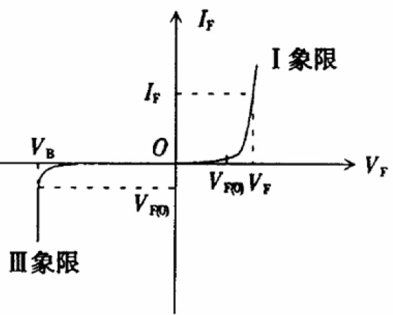
The typical volt-ampere characteristic curve of the illuminated LED is shown in Figure 1. The normal working area of ​​the LED is the VF(0)---VF segment in the figure. It can be seen from the working section that the most effective way to stabilize the operation of the LED is to control the operating current of the LED to stabilize the working point of the LED. Therefore, for a single string of LED modules, a constant current source is used or Dimming is the most reliable method of choice by adjusting the operating current. However, if a constant voltage circuit is used, and the constant current circuit in the LED module is additionally used or used, the LED can be stably operated. At this time, the constant voltage circuit and the constant current circuit in the LED module should be combined. It looks like an LED control unit. Because of the thermal negative resistance of LEDs, simple constant voltage circuits (such as switching power supplies) cannot be used as LED driver circuits.

Figure 1 volt-ampere characteristic curve
In response to the characteristics of the LED module for lighting, the IEC standardization organization issued the IEC 62384:2006 standard. The National Lighting Standardization Technical Committee also completed the drafting and approval of the standard in 2008. The approval of the report not only retains the entire contents of IEC 62384. It also increases the energy efficiency requirements of LED control devices. In this paper, the main content of the draft is to introduce the original provisions of the standard terms, the requirements of the products and the test requirements for the reference of the majority of peers.
First, the output voltage and current
1, startup and connection requirements
The storage capacitors associated with the output in the LED control unit generate short-term surge voltages or surge currents when starting or connecting the LEDs. These surges are not controlled and may shorten or damage the LED life. The assessment of this article is to ensure that the control device is connected to the output load and then connected to the input power supply and then connected to the input power supply, and then the LED load is turned on for a short time without causing short-term overload operation of the LED module.
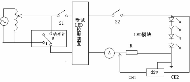
The test is connected as required in Figure 2.

Figure 2 Test circuit for startup and connection process
The test procedure is as follows:
Connect the smallest LED load to the LED control unit. For a control device that controls the output voltage, when there are multiple sets of parallel loads, only a minimum set of loads is left. For control devices that control the output current, the number of LEDs per string in the output loop is minimized (possibly leaving one LED in a string).
Connect one channel CH1 of the digital storage oscilloscope (div) to the current sampling resistor (sampling resistor R≥0.5Ω, no sense resistor), and the other channel CH2 is connected to the voltage sampling end (upper end) of the LED module. The ground terminal of the oscilloscope is connected to the common terminal for voltage/current measurement. Set the digital storage oscilloscope to the automatic trigger sampling mode, recording time ≥ 2s. The integration period is also set to 0~2s.
Note: The oscilloscope's measuring probe should not use a differential isolation probe, otherwise the DC component cannot be acquired.
First close S2, adjust the power supply voltage to the rated value, and then close S1. The effective value recorded by the oscilloscope is the starting current and starting voltage value provided by the control device to the LED module, which should not exceed the rated rating of the LED module used. The value (voltage and / or current) is 1.1 times. At the same time, this measurement must not exceed the nominal maximum output current or maximum output voltage of the LED control unit.
After completing the above measurement, disconnect S1 and S2, wait for 15 minutes, then close S1 first, the oscilloscope setting is the same as above, then close S2. The effective value recorded by the oscilloscope is the connection current when the control device is working and then the LED module is connected. The value of the connection voltage should also not exceed 1.1 times the rated value (current and / or voltage) of the LED module used. At the same time, this measurement must not exceed the nominal maximum output current or maximum output voltage value of the LED control unit.
Note: In the above measurement, the oscilloscope should be set to have the status of measuring AC and DC (including pulsating DC). The measured value should include DC (pulsating DC) and AC component, and the integrated value should be true RMS ( RMS).