 The early small and medium rivers hydrological tests generally used a manually operated hydrological cable test system with long operating time, high labor intensity and subjective error. To this end, we have modified the original manual test system, using the single-chip control instead of manual automatic hydrological test. This paper introduces the automatic test system of hydrological cableway based on ATMEL89 single-chip microcomputer. The design of the system is based on the original facilities, and the system structure is not changed as much as possible and can be compatible with the manual operation method. The calculation and printing of the flow are automatically completed. Two types of hydrological cableways for suspension cables and suspension rods for medium and small rivers.
According to the "Hydrological Cableway Test Specification" issued by the Ministry of Water Resources and the structure and test requirements of the manually controlled hydrological cableway, the main functions of the MCU control system are: automatic area, average flow rate, flow test and calculation printing of the river section; river section Automatic test of water depth, water surface declination, river bottom angle, and average vertical velocity of any vertical line; dry rope, wet rope and displacement correction; automatic monitoring of water level during the test. The hardware of the system is composed of MCU as the core and input/output interface, memory system and print display circuit. The software part consists of four main software modules: system control, data acquisition and storage, error correction and flow calculation.
The principles and design points of the system are described below.
1, system composition
The system block diagram is shown in Figure 1.
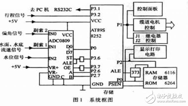
Use AT89S8252 microcontroller. Due to the large amount of data in the river test and the complicated operation, the internal memory capacity of the microcontroller is limited. Therefore, the external memory RAM6116 and the ROM 6264 are added. The input and acquisition interface of the external signal is based on the multi-channel A/D chip ADC0809, and the cable channel signal and the water level signal are sent to the interface of the P1 port and the P3 port of the single chip to bear other input and output signals. The main interface circuits and working processes are introduced below based on the characteristics of the hydrological test.
1.1, ADC0809 interface circuit
The interface circuit centered on ADC0809 is shown in Figure 2.
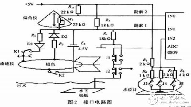
He transmitted the water level change signal of the teletype water level gauge and the flow rate, declination, and water surface signal sent from the cable channel to the MCU. The interface has the characteristics of simple circuit, stable and reliable, and strong anti-interference.
1.1.1. Acquisition of water level signal
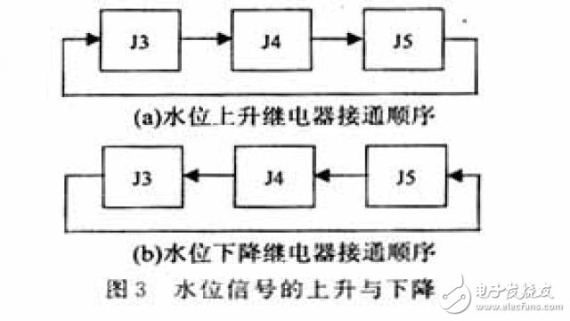
The teleport water level gauge is used to monitor the change of the water level. The sensor part of the teletype water level gauge has been modified in order to obtain the water level signal. Reed relays J3, J4, and J5 are added inside the sensor to cancel the internal battery and directly supply power from the system. The resistors R5~R8 form a voltage divider, and the voltage divider outputs to the ADCIN2 port circuit as shown in Fig. 2. When the water level changes, the float rises and falls, the float rises and falls 3 cm, and the magnetic steel inside the sensor rotates for one week, that is, one reed relay will be turned on and off once every change of 1 cm. When the J3, J4, and J5 are respectively connected, the voltage of the IN2 port is 1.6 V, 2.5 V, and 3.2 V, respectively, and the voltage of the IN2 port is +5 V when there is no relay. According to the voltage value of the ADCIN2 port, it can be determined which reed relay is on and off. It can be known from the voltage change law of the IN2 terminal that the rise or fall of the water level is as shown in Fig. 3. In Fig. 3, (a) is rising and (b) is decreasing.
1.1.2 Acquisition of water surface bottom signal
When measuring the depth of the vertical line, the lead fish starts to descend after it reaches the designated vertical line position of the river section. Once the lead fish touches the water surface, the water depth counter starts to count the water depth. When the lead fish continues to fall into contact with the bottom of the water, the bottom switch closes and stops counting. The count value is the initial value of the water depth of the vertical line. The working process is as follows: During the lead fish drop process, the MCU constantly reads the ADCIN1 port voltage. Before the lead fish enters the water, the relays J1 and J2 are in the normally closed position, and the voltage of the input terminal IN1 of the ADC0809 is determined by the R3 and R4 voltage divisions to be 2.5 V. Once the lead fish touches the water surface +5 V voltage, the voltage of the IN1 terminal rises to 3 V or more through the underwater plate → river water → lead fish → secondary cable 1 → ADC0809. According to the voltage of IN1 port, the MCU judges that the lead fish has contacted the water surface to start the water depth counting, and at the same time, the P3.4 output high level relay J1 is connected to the normally open contact. The circuit diagram shows that the river water resistance is connected in parallel with R4 so that the voltage of the IN1 port is about 1.5 V. . When the lead fish continues to drop until it touches the bottom of the river, the bottom switch K2 is pressed, and the voltage of the ADCIN1 port in the lead Vfish internal 4.5 V battery E1 is reduced to below 0 V. The MCU judges that it has reached the bottom stop water depth count and passed the P1. The port output signal stops the water depth motor.
1.1.3 Acquisition of declination signals
The cableway is equipped with a special declination instrument to correct the water depth measurement error caused by the water flow causing the lead fish not to fall vertically to the bottom of the water. The declimeter can measure the angle of the lead fish from the normal position due to the influence of the water flow, and then correct the water depth error by looking up the table or formula according to the magnitude of the declination. The manual measurement uses the eye to estimate the magnitude of the declination according to the scale of the declimeter, and the error is large. We made a slight change to the declination instrument to add a potentiometer W1 and the corresponding circuit as shown in Figure 1, through the mechanical linkage device to convert the displacement of the declination into the rotation of the potentiometer to change the resistance of W1, using the secondary cable 2 The voltage change due to the change in the yaw angle is sent to the ADCIN0 port. Considering the particularity of field work, a wirewound potentiometer with stable performance and good sealing performance is adopted. Since the voltage change of the IN0 port and the off angle are not linear, the declination value is determined by a software look-up table. In order to reduce the influence of mechanical displacement, cable resistance and other factors, in the actual operation, when the lead fish is not in the water, the angle of deviation is measured as the reference. When the water surface and the bottom of the water are reached, the water surface declination and the bottom angle are measured respectively. Accurate declination value.
1.1.4 Acquisition of flow rate signals
The flow rate is measured by the flow meter. When measuring the flow rate, the relays J1 and J2 are connected to the normally open contact. The voltage of -5 V is applied to the underwater plate. K1 is the internal switch of the flow meter. The K1 is turned on and off once per revolution of the flow meter. . When K1 is off, the voltage of ADCIN0 port is about 1.5 V. When K1 is turned on, the voltage of ADCIN0 port changes more than 0.5 V. As long as the voltage difference of IN0 port is monitored, the rotation of the flow meter can be judged. In the actual measurement, the voltage difference of the IN0 port is related to the distance between the vertical point of the measuring point and the water quality. The larger the distance, the smaller the voltage difference is. The voltage difference of the flow rate signal in the 150 m channel is greater than 0.5 V. The ADC0809 monitors the flow rate signal. When VREF=5V, the resolution is 0.02 V, which is enough to distinguish the rotation of the flow meter. Considering some uncertain interference factors, the resolution of the voltage difference is set at 0.1 V, which can meet the general medium and small river channels. Test requirements. For wider channels, the voltage difference can be increased by improving the circuit or increasing the operating voltage. Interface information composed of a communication interface with a PC, such as:
(1) Travel signal such as water depth and horizontal distance;
(2) water level signal;
(3) The output control signal is used to control the motor to perform forward rotation, reverse rotation, and stop, so that the lead fish can perform fixed point measurement according to the required motion.
The interface circuit is shown in Figure 1. The circuit fully utilizes the ADC0809 multi-channel analog-to-digital converter to convert complex interface information into digital signals. At the same time, the photoelectric door is used to convert the working cable stroke (the movement of water depth and horizontal distance) into an electrical pulse signal, and sent to the ATMEL89 single-chip microcomputer for processing, display and control to complete the automatic test.
1.2 Acquisition signal interface circuit
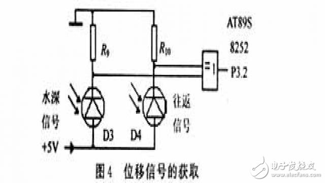
The stroke signal of the lead fish includes the stroke signal of the horizontal movement of the lead fish, and the water depth signal of the lead fish moving vertically when measuring the water depth. The acquisition of the displacement signal is shown in Figure 4. He is obtained from a cutting plate and a photoelectric door attached to a mechanical transmission. Designed to block the cable for 1 cm per movement, the photogate produces a pulse. The water depth and the round-trip signal are taken out from the photodiodes D3 and D4 respectively, and are added to the external interrupt 0 input terminal of the single-chip microcomputer P3.2 after the XOR gate. An interrupt is generated for each movement of 1 cm. The interrupt service routine can distinguish the lead fish at this time. Move back and forth or move vertically, only one of them.
1.3 Other circuit parts
The input function of the P1 port is to read the operation command and the initialization value from the control panel, and the output function is to output the control signal. The first is to control the forward, reverse and stop of the stroke motor, so that the lead fish can perform vertical and horizontal movement according to the test requirements; the second is to control the closing and opening of the relays J1 and J2 to obtain the surface water bottom signal during the water depth measurement. The display print circuit section uses 6 LED tube displays and a micro printer for simple printing. Connect to the PC with the P3.1 serial port for data transfer and further processing, display and printing.
2 system software flow chart
The software of this system accounts for about 7 kB, and the system program flow chart is shown in Figure 5.
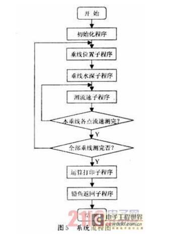
The program is divided into three major modules: system management, arithmetic processing, and test control. The system management module includes: initialization, system monitoring, operation switching, emergency processing and the like. The arithmetic processing module includes: a program of data calculation, error correction, display printing, and the like. The test control module is composed of many subroutines including: measuring the vertical line to the starting point, measuring the water depth of the vertical line, measuring the vertical line flow rate, measuring the vertical line water level, and collecting the interface data.
In order to minimize the measurement error and ensure that the measurement accuracy is strictly in accordance with the requirements of the hydrological specification, a secondary water inlet operation is adopted in the submerged water depth subroutine program. The program flow is shown in Fig. 6.
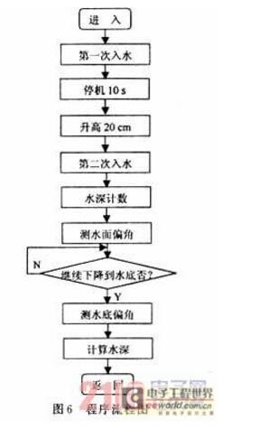
In the actual water depth measurement, the measurement error is caused by the movement of the lead fish due to the movement of the lead fish. The operation set in the program is: when the lead fish is suspended in the water, it will not count the water depth for 10 s, and wait for it to stabilize and then rise. The water surface is 20 cm and then enters the water surface for the second time. After the lead fish reached the water surface for the second time, the water depth count paused and the water surface deviation angle θA was measured. The lead fish continued to fall until the bottom of the river stopped counting the water depth, and the bottom angle θB was measured. Finally, according to the length of the dry rope (the height of the cable to the water surface), the length of the wet rope (the initial value of the water depth), θA, θB, the actual depth of the vertical line is calculated.
3, the conclusion
The ATMEL89 single-chip hydrological cable test system has strong compatibility. It is suitable for automatic or semi-automatic test of medium and small rivers. It has convenient operation and stable performance. The test accuracy meets the requirements of the Ministry of Standards, which effectively reduces the labor intensity of the operator. operating hours.
Guangdong Ojun Technology Co., Ltd. , https://www.ojunconnector.com