1 Research background
With the increasing environmental and energy issues, electric vehicles and renewable energy have received widespread attention and rapid development. The electric vehicle charging and discharging integrated power station combines the advantages of electric vehicle charging station and two-way power station, realizes energy bidirectional dispatching of electric vehicles and power grids, and provides the best solution for large-scale application of renewable energy power generation and electric vehicles.
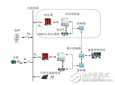
The research object of this paper is the parallel power regulation system (PCS) in the electric vehicle charging, discharging and storage integrated power station. The system consists of multiple bidirectional converter sub-modules in parallel, using a centralized control structure. According to the upper energy management system (EMS) scheduling, the system can work in a variety of operating modes. The paper deeply analyzes the parallel high-power bidirectional power regulation system in the electric vehicle charging and discharging integrated power station independent operation, grid-connected operation and grid-connected operation. Control strategy in the process of seamless switching from independent operations.

Parallel power regulation system structure in electric vehicle charging and discharging integrated power station
2 operating mode and control strategy
V2G mode and control strategy
When the V2G is running, the PCS adopts the inverter side inductor current inner loop PI and the grid side inductor current outer loop PI control mode, and the upper layer power station EMS issues the bidirectional unit active/reactive power command. This double closed-loop control method can effectively suppress the grid current resonance and achieve high power factor operation of the grid side current, and at the same time have good steady state and dynamic performance. When the battery is charged, the converter operates in a voltage-type high-frequency pulse width modulation (PWM) rectifier state, and when it is discharged, it operates in an inverter state, and the four-quadrant operation characteristic of the high-frequency PWM converter can realize the conversion of the charge and discharge state. In this mode of operation, the PCS can absorb or supply a certain amount of active power and reactive power from the distribution network according to the needs of the power station to maintain the tidal current stability of the public connection between the power station and the distribution network (PCC). It becomes a controllable unit relative to the grid.
Independent mode and control strategy
The PCS operates independently using the dual-loop control method of the inverter side inductor current inner loop PI and the capacitor voltage outer loop PI. This double closed-loop control method can achieve good system output voltage waveform quality and improve the dynamic performance of the system. At this time, the converter is a voltage source operating mode, and the parallel system has two key problems of synchronization and current sharing. The digital synchronous control scheme is adopted, and the power frequency square wave signal generated by the centralized controller is photoelectrically converted and sent to the bidirectional converter controller for receiving. In order to achieve power sharing between modules in parallel systems, power sharing control is introduced. The average power control strategy depends on the output power and output impedance of each PCS module.
Seamless switching mode and control strategy
The PCS seamless switching control system consists of two parts, a voltage control unit and a current control unit. In order to achieve a seamless switching process between the grid-connected operation and the independent operation, the inner loop of the inductor current is maintained, and the outer loop switches between the grid-side inductor current loop and the filter capacitor voltage loop and performs command tracking. In the independent operation mode, when receiving the EMS grid-connected operation scheduling command, the bidirectional converter detects the voltage amplitude and phase of the distribution network, and adjusts its own output voltage amplitude and phase with reference to this. When the grid-connected condition is met, the static switch is triggered. At the same time, the bidirectional converter switches the capacitor voltage outer loop PI to the grid-connected inductor current PI control based on the inverter inductor current inner loop PI, realizing the double loop seamless from independent to grid-connected. Switching process. Fast and accurate grid state detection and phase lock control can reduce grid-connected impact and achieve smooth mode switching. In the grid-connected operation mode, the microgrid is disconnected from the distribution grid when a grid fault is detected or planned maintenance is performed. The bidirectional converter is still switched from the grid-connected inductor current outer loop to the capacitor voltage outer loop on the basis of the inverter inductor current inner loop PI, and smoothly switches into the independent operation mode.
3 Simulation and experimental verification
With the microprocessor TMS320F2812 as the core control device, two 500kVA PCS parallel test systems were built.
In the V2G mode, the PCS is the current mode converter operating mode, and the grid power command is issued by the centralized controller. The experimental waveforms of the charging and discharging process show that the system can obtain a good waveform of the incoming current waveform and a high power factor.
In the independent mode, PCS is the working mode of the voltage source converter. The off-grid dynamic experimental waveform shows that the system can guarantee good voltage waveform quality and quickly respond to load fluctuations in the station. In the process of load abrupt change, the current can achieve instantaneous equalization and has good dynamic performance.
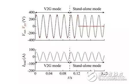
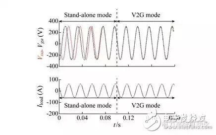
It can be seen from the experimental waveforms of the V2G operation mode and the independent operation mode switching process in the following figure that the double-loop seamless switching scheme proposed in this paper can achieve stable and smooth voltage transition, and provide guarantee for the stable operation of the integrated power station.

V2G operation mode switches to independent operation mode process experiment waveform

Independent operation mode switches to V2G operation mode process experiment waveform
4 Conclusion
The power regulation system is the core power conversion device of the electric vehicle charging, discharging and storage integrated power station. It is responsible for the charging and discharging of electric vehicles, battery energy storage and ladder utilization, and peaking and valley filling. In this paper, the control strategy and control model of V2G operation, independent operation and seamless switching mode between modes are analyzed in depth. Based on the three-phase converter topology using LCL filtering, a double-loop seamless switching control strategy including inverter-side filter inductor current inner loop, filter capacitor voltage outer loop and grid-connected inductor current outer loop is proposed. Switching conditions and switching procedures for switching. The research results show that the power control system control strategy proposed in this paper can realize the economic and reliable operation of the electric vehicle charging, discharging and storage integrated power station.
Pc Material,Pc Plastic Material,Pc Clear Material,Pc Material Properties
WENZHOU TENGCAI ELECTRIC CO.,LTD , https://www.tengcaielectric.com