The 2-way speaker refers to a speaker consisting of a tweeter and a woofer. It is a kind of full-range speaker.
Self-made two-way frequency divider simple version
Today, I present a self-made bass crossover for everyone. Although the material is not much and simple, the bass effect is extremely strong.

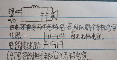
Because the circuit needs 2 electrodeless capacitors, I don't have electrodeless capacitors, so I use 4 50v10uf capacitors in series instead of electrodeless capacitors.
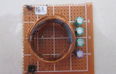
Hole board.
A mold for winding coils.

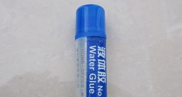
Because I only took pictures after the things were done, there was no picture of winding the coil. The winding method of the coil was 20 turns from the inside to the outside, 5 layers, and the middle was reinforced with 502. After winding, remove the layer of film and coil on the glue bottle, tear off the film, and the coil will be born. The wiring of the coil is an external MP3 pin, internally connected with a capacitor and a speaker.

Components required to make a two-way frequency divider
1. Material preparation
According to the designed frequency divider schematic diagram, prepare the following materials:
1. According to the requirements of inductance coils, select suitable non-metallic skeletons for the inductor skeleton, such as solder wire, plastic skeleton of raw material tape for sealing, and other wood and glue skeletons.
2. Select enameled wires of appropriate thickness and high quality for the enameled wire (the author chose the enameled wire removed from the switch of the car starter).
3. Select capacitors and resistors with suitable capacity, resistance and power for the resistance-capacitance components according to the circuit requirements. The frequency-division capacitors are best to use imported or domestic high-quality CBB capacitors, and high-power cement resistors are the first choice for resistors.
4. Adhesive This agent can choose a commercially available "Lide Lao" and other strong viscosity glue.
5. Coins, bolts and bolts should be made of copper with a diameter of about 4mm, and their length is determined by the height of the inductor skeleton.
6. Copper-clad board According to the number of frequency-dividing components, select a high-quality copper-clad board with a suitable size, and the line direction is engraved with a utility knife according to the design requirements.
7. A plate of scotch tape.
Two, production
1. Drill a small hole slightly larger than the enameled wire in the middle of the top and bottom of the adhesive bottle around the inductor (the liquid will not flow out of the hole because the liquid is thick). After passing a piece of plastic hose in each of the two holes, remove the enameled wire Pass through the two rubber tubes to ensure that the enameled wire is not scratched when passing through the two holes. Then one person can tighten one end of the enameled wire, and the other person can take the other end of the enameled wire and wind the wire on the frame. Do not touch the enameled wire with both hands during winding. The enameled wire has been evenly coated with a layer of adhesive when it passes through the adhesive. You can pinch the two ends of the frame to rotate it. After the number of inductance turns is enough, cut off the excess enameled wire and fix the outer lead wire. After the adhesive on the wire has solidified, use scotch tape to tightly wind several layers on the coil.
2. Component installation According to the position of the inductor coil and the resistance and capacitance parts on the board, use a small drill to make a hole on the board, drill a hole slightly larger than the diameter of the copper bolt in the middle of the coin, and then pass the copper bolt through the coin, Coil and circuit board, then pad with spring washer, fasten with nut, scrape the lead wire of coil, capacitor and resistor and solder them on the corresponding position, and finally solder the incoming and outgoing wires on the board.
After the above operations, a high-quality and low-cost crossover is completed, and the rest is the joy of experiencing success.
Interactive Smart Board,Smart Boards,Smart Board Projector,Smart Electric Board
APIO ELECTRONIC CO.,LTD , https://www.displayapio.com