This article mainly introduces the relevant knowledge about the classification of the interference power filter, and focuses on the description of the interference power filter series.
The concept of filteringFiltering is an important concept in signal processing. The function of the filter circuit is to reduce the AC component of the pulsating DC voltage as much as possible, retain its DC component, reduce the output voltage ripple coefficient, and make the waveform smoother.
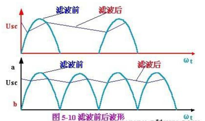
Generally speaking, filtering is divided into classic filtering and modern filtering.
Classical filtering is an engineering concept based on Fourier analysis and transformation. According to advanced mathematics, any signal that satisfies certain conditions can be seen as a superposition of infinite sine waves.
In other words, the engineering signal is the linear superposition of sine waves of different frequencies. The sine waves of different frequencies that make up the signal are called the frequency components of the signal or the harmonic components. A circuit that only allows signal components within a certain frequency range to pass normally while preventing another part of the frequency components from passing is called a classic filter or filter circuit.
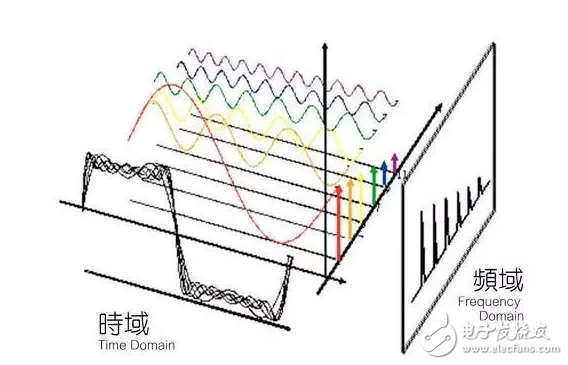
In classic filtering and modern filtering, the filter model is actually the same (hardware filters have not made much progress), but modern filtering also adds many concepts of digital filtering.
Power filterThe basic principle of power filter
The power filter is composed of a low-pass filter circuit composed of inductors and capacitors. It allows DC or 50Hz current to pass, and has a greater attenuation of interference signals with higher frequencies. Since there are two kinds of interference signals, differential mode and common mode, the power filter must attenuate both types of interference.
Main indicators of power filter
When we choose a power filter, we should mainly consider three indicators; the first is the voltage/current, the second is the insertion loss, and the last is the size of the structure. Since the inside of the filter is generally potted, the environmental characteristics are not a major issue. However, the temperature characteristics of all potting materials and filter capacitors have a certain impact on the environmental characteristics of the power filter.
The influence of voltage and current on the use effect
The power supply is divided into AC and DC. Correspondingly, many manufacturers' power filters are also divided into AC and DC. In principle, the AC power filter can be used on both AC and DC power supplies; however, the DC power filter cannot be used in AC applications, mainly because the capacitors in the DC filter have lower withstand voltage , And it is possible that its AC loss is relatively large, resulting in overheating. Even if there is no problem with the withstand voltage of the DC filter, since a large-capacity common-mode filter capacitor is used in the DC filter, the leakage current will exceed the standard in an AC situation. Therefore, the DC power filter must not be used in AC applications. AC filters are used in DC applications. From a safety point of view, there is no problem, but at the expense of cost and volume; in the prototype stage, if you have an AC filter on hand, you can replace the DC filter.
When the working current of the power filter exceeds the rated current, it will not only cause the filter to overheat, but also reduce the low-frequency filtering performance of the filter. This is because the inductance in the filter will saturate in the case of a large current, which reduces the actual inductance. Therefore, when determining the rated working current of the filter, the maximum working current of the device shall prevail to ensure that the filter has good performance under the maximum current state, otherwise the equipment will be interfered when interference occurs under the maximum working current state. Or the conducted emission exceeds the standard.
When determining the rated current of the filter, it is necessary to leave a certain margin; in particular, people are used to refer to the alternating current as the "effective value" instead of the "peak value" of the alternating current. It is very necessary to leave a certain margin. Generally, the rated current value of the filter should be 1.5 times the actual current value.
Interference power filter classificationFeedthrough capacitor-feedthrough filter
Feed-through filters are often used in some high-frequency processing modules such as mobile communication equipment and radar navigation. They cooperate with shielding structures to process input or output low-frequency signals. They are products that other forms of capacitors cannot replace. Now that the working frequency of electronic circuits and the electromagnetic interference frequency in the surrounding environment are getting higher and higher, the problem of insufficient high-frequency filtering exposed by the installation of the filter on the circuit board is more prominent. In order to obtain a better filtering effect in the UHF or higher frequency band, especially when protecting the shield from being penetrated, a feed-through filter must be used.
The feed-through filter is installed on a metal panel and has a very low ground impedance, and the input and output of the filter are isolated by the metal panel, so the filter has a very good high-frequency filtering effect. The circuit structure of the feedthrough filter is divided into C type (through-core capacitor), L-shaped (one through-core capacitor plus one inductor), T-shaped (two inductors plus one through-core capacitor), π-shaped (two through-core capacitors) Add an inductor), etc.; the more components of the filter, the shorter the transition band of the filter, and the greater the insertion loss of the stop band. Among them, the C-type feedthrough filter is generally a feedthrough capacitor.
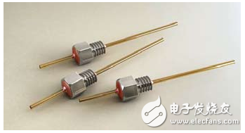
Feedthrough capacitor
The filtering effect of any capacitor with leads will be limited by the ground inductance. As shown in Figure 1, the grounding of the capacitor is formed by connecting the outer surface of the capacitor directly to the metal shield or panel by screwing or welding. Since the ground current is dispersed in the 360° range around the center conductor, there is actually no lead inductance, and the capacitor can maintain good performance in a very high frequency range.
There are three ways to use feedthrough filters:
1) Install on the panel of the shielding body (shielding box, shielding case, etc.). This is the most basic method of use. When a wire passes through the shield, it is necessary to install a feed-through filter on the panel of the shield so that the wire passes through the shield through the feed-through filter.
2) It is installed on the ground layer of the circuit board, and the ground layer of the circuit board can be used as the isolation layer and the ground layer.
3) Installed on the isolation board between the circuits.
When the conditions are not met, the feed-through filter cannot be installed on the shield panel or the ground plane, and the installation on the metal partition also has the incomparable high-frequency filtering effect of ordinary capacitors (including three-terminal capacitors).
There are two types of feedthrough filters: welded installation and threaded installation. The advantages of welding installation are space saving and reliable filtering performance. However, when the filter is welded to the panel, since the heat capacity of the panel is much greater than the heat capacity of the filter, the local temperature of the welding may reach very high, which may easily cause damage to the feedthrough filter. When welding, pay attention to controlling the welding time and temperature. The threaded installation method is simple and easy. You can drill a hole on the panel and screw the feedthrough filter with a nut; you can also directly drill a threaded hole on the panel to screw the feedthrough filter directly on the box or panel. Pay attention to two points when installing. One is that the torque should not be too large. Although the feedthrough filter is as strong as a screw from the outside, it is time-hollow inside, and excessive torque will cause damage. The second is to put on serrated gaskets during installation, so that good contact can be maintained.
When selecting the circuit form of the feedthrough filter, it is generally based on the following conditions:
1) Attenuation to interference: The more components of the filter, the greater the attenuation of interference signals.
2) The difference in frequency between the useful signal and the interference signal: the smaller the frequency difference between the useful signal and the interference signal, the greater the number of components that need filters.
3) Impedance of the circuit using the filter: A basic principle is that the capacitor in the filter faces the high-impedance circuit and the inductor faces the low-impedance circuit. The so-called high and low here can be referred to as 50Ω.
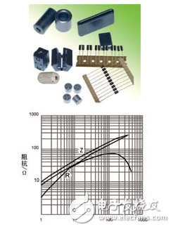
EMI suppresses the impedance component of ferrite ferrite changes with frequency
EMI suppression
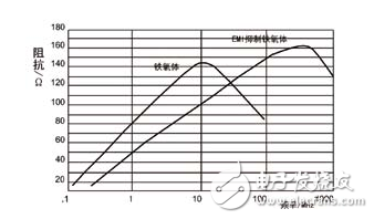
Ferrite uses ferrite (shown in Figure 2) to have a large loss in high-frequency electromagnetic fields and has a strong absorption effect on interference energy. This material is widely used in interference suppression of electronic equipment. Due to the absorption (not reflection) of high-frequency waves by ferrite, the Q value of the inductance suppression circuit in the circuit can be reduced, and the problem of signal resonance can be reduced. EMI suppression ferrites have the opposite characteristics of low-loss inductive materials used in low-frequency or power supplies. Figure 3 shows how the resistance component determines the impedance characteristics at high frequencies.

Use of ferrite
Putting a ferrite magnetic ring on the wire or cable constitutes a simple, economical and easy to install filter, as shown in Figure 4. The function of ferrite is to concentrate the magnetic field around the wire, thereby increasing the inductance of the wire hundreds of times. The biggest advantage of ferrite chokes is that they do not need to redesign the circuit or redesign the structure, so they are widely used in the improvement of equipment. The manufacturer provides a variety of split ferrites with different inner diameter specifications, and the general inner diameter ranges from 5mm to 13mm. When the signal line and the return line pass through the ferrite at the same time, the ferrite pairs the signal (different
Mode) has no effect, but it will increase the impedance of the common mode current. The effect of ferrite can be strengthened by winding the cable a few more times on the ferrite or using a few more ferrites. But the improvement effect of increasing the number of turns is limited by the parasitic capacitance.
The effect of ferrite increases with increasing frequency. The impedance of a ferrite choke coil is usually tens of ohms at 10MHz. When the frequency exceeds 100MHz, the impedance rises to hundreds of ohms (the specific value depends on the shape and size, the larger the ferrite volume, the greater the impedance) . Different manufacturers' products or different types of ferrites from the same manufacturer have different impedance changes with frequency. Figure 5 shows the characteristics of two ferrites with the same size (outer diameter of 5mm, length of 11mm) but different materials.
Since a ferrite choke is just a high-loss inductor, it only works in low-impedance circuits. Used in high-impedance circuits, its effect is very poor or even ineffective. Most circuits, especially cables, have complicated changes in impedance with frequency, and are usually in the range of 10 to 1,000 Ω. Therefore, the attenuation provided by a single ferrite is very limited, generally around 10dB, rarely more than 20dB. Ferrite chokes are effective in reducing the rapid rise rate of ESD current pulses. This ESD interference may be induced into the internal cables. Transient parameters will be absorbed by ferrite instead of shunting or reflecting to other parts of the system.
To give full play to the performance of ferrite, the following precautions are very important:
1) The effect of the ferrite bead (magnetic bead) is related to the impedance of the circuit: the lower the impedance of the circuit, the better the filtering effect of the ferrite bead or the ferrite bead. Therefore, in the general ferrite material product manual, the insertion loss of the ferrite material is not given, but the impedance of the ferrite material is given. The larger the impedance of the ferrite material, the better the filtering effect. .
2) The influence of current: When a large current flows through the ferrite wire, the low-frequency insertion loss of the filter will become smaller, and the high-frequency insertion loss will not change much. To avoid this situation, when using the power cord, you can pass the power cord and the power return line through the ferrite at the same time.
3) Selection of ferrite materials: According to the frequency of interference suppression, choose ferrite materials with different permeability. The higher the magnetic permeability of the ferrite material, the greater the impedance at low frequencies and the smaller the impedance at high frequencies.
4) Determine the size of the ferrite magnetic ring: the greater the difference between the inner and outer diameters of the magnetic ring, the longer the axial direction and the greater the impedance. But the inner diameter must be tightly wrapped. Therefore, in order to obtain a large attenuation, use a larger magnetic ring as far as possible under the premise that the inner diameter of the ferrite magnetic ring is tightly wrapped.
5) The number of turns of the common mode choke: Increasing the number of turns passing through the magnetic ring can increase the low-frequency impedance, but due to the increase of the parasitic capacitance, the high-frequency impedance will decrease. It is a common mistake to blindly increase the number of turns to increase the attenuation. When the interference band to be suppressed is wider, different numbers of turns can be wound on the two magnetic rings.
6) The number of ferrite magnetic rings on the cable: increasing the number of ferrite magnetic rings on the cable can increase the low-frequency impedance, but the high-frequency impedance will decrease. This is because of the increase in parasitic capacitance.
7) The installation position of the ferrite ring: generally try to be as close to the interference source as possible. For the cable on the shielded case, the magnetic ring should be as close as possible to the cable inlet and outlet of the case. It is better to use with capacitive filter connector: Since the effect of ferrite magnetic ring depends on the impedance of the circuit, the lower the impedance of the circuit, the more obvious the effect of the magnetic ring. Therefore, when capacitive filter connectors are installed at both ends of the original cable, the impedance is very low, and the effect of the magnetic ring is more obvious.
ConclusionThis is the end of the introduction to the classification of interference power filters. I hope this article can help you. If you have any deficiencies, please correct me.
Rack Mount Battery,Home Energy Storage Battery,Residential Energy Storage Systems,Home Energy Storage Systems
JIANGMEN RONDA LITHIUM BATTERY CO., LTD. , https://www.ronda-battery.com