Overview:
This paper introduces a waveform control technology of inverter based on harmonic compensation, analyzes the working principle of the system, discusses the design method of control system parameters in detail, and obtains the test results. The inverter is an important DC/AC converter. An important measure of its performance is the quality of the output voltage waveform. A good inverter, its output voltage waveform should be as close as possible to the sine, and the total harmonic distortion rate (THD) should be as small as possible. In practical applications, the inverter often needs to be connected to a rectified load. In this case, the inverter with only SPWM modulation technology will have a large distortion of the output voltage waveform. In order to obtain a small THD output voltage, waveform control technology has been greatly developed in recent years. Repetitive control is a control scheme that has been studied in recent years. From the perspective of harmonic compensation, this paper uses the improved FFT algorithm to perform real-time spectrum analysis on the output voltage error signal, and injects the predistorted harmonic signal generated by the software algorithm into the inverter, thereby suppressing the nonlinear disturbance. Correct the purpose of the output voltage waveform. 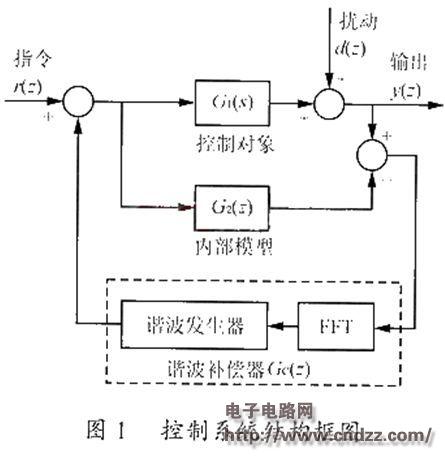
G1(s) represents the control object, here is the transfer function of the output LC filter, and its discretization form is represented by G1(z). G2(z) represents the internal model, which is equal to G1(z).
1 Disturbance suppression principle: Consider the response of the disturbance signal d(z) at the output point. The transfer function of the disturbance signal Hd(z)=1-{[Gc(z)G1(z)]/1+[G1(z)-G2(z)]Gc(z)} can be easily obtained from Fig. 1 1) Since G1(z)=G2(z), Hd(z) can be simplified to Hd(z)=1-Gc(z)G1(z) (2) Obviously, as long as Gc(z)=G1-1 (z), then Hd(z) = 0, that is, the disturbance can be completely suppressed. Unfortunately, the z-domain transfer function of the actual inverter contains a purely delayed link, which means that the harmonic compensator Gc(z) must contain a leading link, which is physically impossible. However, in practical applications, we only need to suppress the low-order harmonics to obtain a better output voltage waveform. Therefore, it is only necessary to make the low-frequency characteristic of the harmonic compensator to control the low-frequency characteristics of the object G1(s). . This is very easy to do, and this article refers to the reverse of the low frequency band characteristics as "equivalent inverse".
2 Internal model: The internal model G2(z) is equal to the discretized form G1(z) of G1(s), which functions to simulate the characteristics of the control object as a reference signal source. In the actual system, the internal model is implemented as part of the overall digital control system by DSP software algorithms.
(Please read the PDF for details)
Guangzhou Yunge Tianhong Electronic Technology Co., Ltd , http://www.e-cigaretteyfactory.com