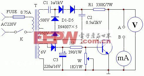
 The simple withstand voltage tester circuit is shown in the figure. The circuit can conveniently measure the back pressure of triode, diode, Zener, thyristor, etc.; capacitor withstand voltage; resistance greater than 10MΩ. The output voltage is continuously adjustable up to 1400V. The simple withstand voltage tester circuit is shown in the figure. The circuit can conveniently measure the back pressure of triode, diode, Zener, thyristor, etc.; capacitor withstand voltage; resistance greater than 10MΩ. The output voltage is continuously adjustable up to 1400V. The working principle is as follows: after the 6V of the transformer T is D5 rectified and C3 filtered, the base voltage of the adjusting tube Q is provided. Adjust W to control the degree of conduction of Q. That is, the control collector A point changes the voltage between 4V and 1400V. The 500V voltage output from the high voltage winding is rectified by a voltage doubler rectifier circuit composed of C1, D1-D4, and the C2 filter output is 1400V high voltage. During the test, the device under test is connected between A and B. When the resistance value of W is small, the base potential of Q decreases, and the potential of point A rises. Until the milliampere meter indicates the rated reverse current of the tube under test (the measured small power tube <0.1mA, high power tube <1mA is appropriate). At this time, the voltage value indicated by the voltmeter is the back pressure at the reverse current. When measuring the resistance value, the resistance is connected between A and B, and the voltmeter reading is divided by the milliampere meter reading. Unit: Ω=V/A. After each run out, set W to maximum and return the output voltage to the low 4V. |
Metal Spraying Accessories,Pump Sprayer,Pressure Sprayer,Agriculture Sprayer Parts
Shaoxing Tianlong Tin Materials Co.,Ltd. , https://www.tianlongspray.com