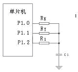
The application of single-chip microcomputers in electronic products has become more and more extensive. Temperature detection and temperature control are also used in many electronic products. However, those temperature detection and control circuits are usually complicated and costly. This paper provides a low cost. The temperature detection circuit realized by the redundant I/O port of the single chip is very simple and easy to implement, and is applicable to almost all types of single chip microcomputers. Its circuit is shown below:

In the picture:
P1.0, P1.1 and P1.2 are the three I/O pins of the microcontroller;
RK is a precision resistor of 100k;
RT is 100K - 1% thermistor;
R1 is a normal resistance of 100Ω;
C1 is a 0.1μ ceramic dielectric capacitor.
Its working principle is:
1. First set P1.0, P1.1, P1.2 to low level output, so that C1 is discharged to the end.
2. Set P1.1 and P1.2 to input state, P1.0 to high level output, charge C1 through RK resistor, the internal timer of the MCU is cleared and starts timing, and the status of P1.2 port is detected. When the P1.2 port is detected as a high level, that is, when the voltage on C1 reaches the gate voltage of the high-level input of the single-chip microcomputer, the single-chip timer records the time T1 from the start of charging to the transition of the P1.2 port to the high level.
3. Set P1.0, P1.1, and P1.2 to low level output to discharge C1 to the end.
4. Set P1.0 and P1.2 to the input state, P1.1 to the high level output, charge C1 through the RT resistor, the internal timer of the MCU is cleared and starts timing, and the status of P1.2 port is detected. When the P1.2 port is detected as a high level, the MCU timer records the time T2 from the start of charging to the transition of the P1.2 port to the high level.
5. The voltage formula from the capacitor:
Can be obtained: T1/RK=T2/RT, ie RT=T2×RK/T1
The resistance value of the thermistor RT is calculated by a single chip microcomputer. And the temperature value can be obtained by the look-up table method.
It can be seen from the above that the error of the temperature measuring circuit is in these aspects: the timer precision of the single chip microcomputer, the precision of the RK resistor, the precision of the thermistor RT, and the output voltage value and the gate embedded voltage value of the single chip microcomputer. The capacitance accuracy is irrelevant. Therefore, the accuracy of the thermistor and the precision resistor is appropriately selected, and the operating frequency of the single chip microcomputer is high enough to obtain a good temperature measurement accuracy.
When the MCU selects 4M working frequency, RK and RT are 1% precision resistors, the temperature error can be less than 1 °C.
If P1.2 has the function of external rising edge interrupt, the program can be simpler and better.
The program flow chart of the operation of the single chip microcomputer is as follows:

Usb Charger Outlet,Usb Outlet,Usb Plug Socket,Usb Wall Outlet
Lishui Trimone Electrical Technology Co., Ltd , https://www.3gracegfci.com