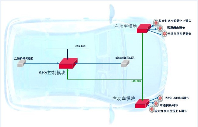
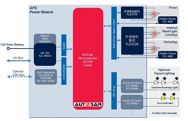
Stepper motors are divided into variable reluctance (VR), permanent magnet (PM) and hybrid (Hybrid) stepper motors. In the automotive environment, the most commonly used is a permanent magnet type stepper motor whose rotor is a permanent magnet. In automotive applications, there are many occasions where stepper motors are required, such as AFS headlamp horizontal position adjustment, corner adjustment, and light geometry adjustment, all requiring a stepper motor as the actuator. Figure 1 is a schematic diagram of a typical AFS system. Figure 2 shows Infineon's chipset solution for AFS applications.
As a leading automotive semiconductor supplier, Infineon has developed a stepper motor dedicated control chip TLE4729G to solve automotive stepper motor control and drive problems. This controller has a range of excellent performance and is used by most component suppliers in system integration.


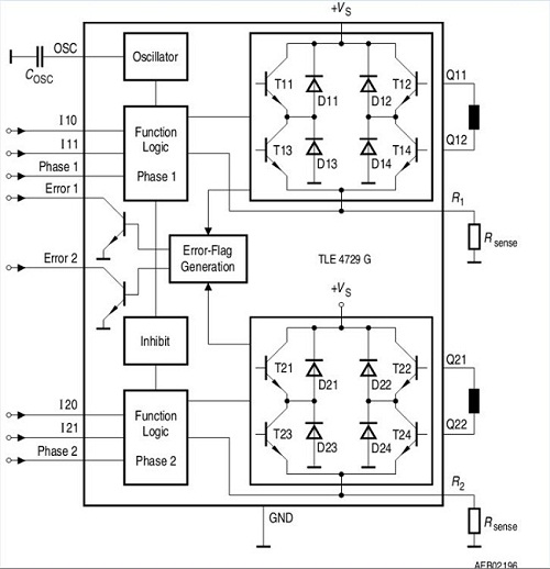
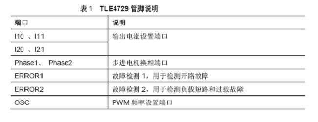
Infineon also provides a number of application notes in addition to the basic data sheet of TLE4729G to facilitate the rapid design of the system. This article explains and explains the stepper motor system and diagnostic points based on the evaluation board. A complement to Infineon's stepper motor control technology support. TLE4729G is used to control and drive the intelligent power device of two-phase stepping motor. Its internal structure is shown in Figure 3. Among them, the important port descriptions related to the application are shown in Table 1.


The products can provide various specifications of rectifier bridge devices according to customer requirements. The electrical properties, appearance, reliability, safety indicators and environmental protection indicators of the products all meet the relevant standards.
Planar Die Construction Sealed Glass Case Ideally Suited for Automated Insertion - 75V Nominal Zener Voltages
Case: MiniMELF, Glass Terminals: Solderable per MIL-STD-202, Method 208 Polarity: Cathode Band Approx. Weight: 0.05 grams= 25°C unless otherwise specified Symbol Pd VF RqJA Tj, TSTG Value to +175 Unit mW V K/W °C
Characteristic Forward Voltage = 200mA Thermal Resistance, Junction to Ambient Air (Note 2) Operating and Storage Temperature Range Notes:
1. Tested with Pulses, 20ms. 2. Valid provided that Electrodes are kept at Ambient Temperature.
1. Tested with pulses = 20 ms. 2. Valid provided that electrodes are kept at ambient temperature.
VZ, ZENER VOLTAGE (V) Fig. 1, Zener Current vs Zener Voltage
25 20 VZ, ZENER VOLTAGE (V) Fig. 8, Zener Current vs Zener Voltage
TA, AMBIENT TEMPERATURE (°C) Fig. 3, Power Dissipation vs Ambient Temperature
15 20 VZ, ZENER VOLTAGE (V) Fig. 4, Differential Zener Impedance
VZ, ZENER VOLTAGE (V) Fig. 5, Junction Capacitance vs Zener Voltage
MINI MELF,Smd mini melf,zener mini melf,mini melf package,mini melf resistor,mini melf diode,mini melf resistor datasheet
Changzhou Changyuan Electronic Co., Ltd. , https://www.cydiode.com