The smart bracelet is a wearable smart device. Through this device, users can record real-time data such as exercise and sleep in daily life, and synchronize these data with mobile phones and tablets to play a role in guiding healthy living through data. In addition, the smart bracelet also has a social function to send workouts and sleep quality to the social network for sharing.

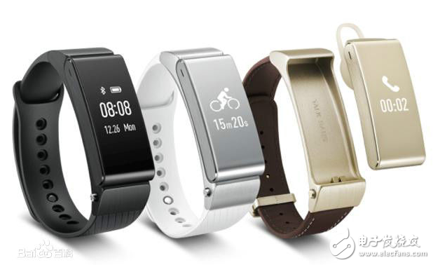
Figure 1_1 A smart bracelet
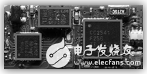
A smart bracelet minimum system generally includes: a rechargeable power module, a control module (left chip in Figure 1_2), a Bluetooth module (right chip), a memory module, and an accelerometer module (top chip). The accelerometer is used to obtain the acceleration data of the wearer during exercise or sleep. By analyzing the data, the wearer's movement and sleep quality can be judged; the storage module is mainly responsible for temporarily storing the real-time data, and then using the appropriate time. The Bluetooth module syncs the data to the mobile phone. For convenience, this step-by-step bracelet will not use memory staging, but will transfer the data to the mobile phone in real time. At the same time, in order to facilitate the understanding of the step-by-step algorithm, the client will display the data collected by the step bracelet in real time in the form of a line chart.

Figure 1_2 A smart bracelet core circuit board
2, how to achieve stepLooking at the above analysis, you may be wondering - how can you achieve step and sleep quality testing with just one accelerometer? In fact, it can be! Because the accelerometer can get its own X\Y\Z three axial accelerations in real time. When it is stationary, the acceleration will fluctuate around the acceleration of gravity; when the wearer is in deep sleep, its acceleration will appear to be stable near the acceleration of gravity for a long time; when it is with the arm of the wearer of the movement When the swing is sexual, the data also has certain rules to follow. In this way, the recording of the quality of exercise or sleep can be achieved by analyzing the data obtained from the accelerometer.
3. Expected effect conceptAs mentioned above, for convenience, we did not use the memory to implement the offline recording of the step bracelet, but to send the data to the client in real time and dynamically draw the result by a visual line graph. As shown in Figure 3_1, the step-by-step part of the system includes a single-chip module, a Bluetooth module, an accelerometer module, and a power module. This allows the data of the accelerometer module to be transmitted to the client program in real time via Bluetooth through the coordination of the single-chip microcomputer. In the client part, it is responsible for dynamically displaying the collected real-time data in the form of a line chart. In addition, a slider is added to the client to control the step threshold to truly understand the design idea (real commercial intelligence). Most of the bracelets use the first step to save the valid data in the small memory of the wristband. The host computer periodically collects and synchronizes the data to the server.

Figure 3_1 Expected renderings
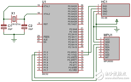
4, the overall design of the hardwareAs shown in Figure 4_1, the hardware configuration is simpler than the previous wireless small fan: the Bluetooth module still uses the familiar HC-06 module. For the measurement of acceleration, the MPU6050 module commonly used in four-way aircraft is used. This module not only has the function of accelerometer, but also has the function of gyroscope. It has applications in many aspects such as anti-rollover, camera pan/tilt, robot balance, air mouse, gesture recognition, etc. Here we just use it. Accelerometer function. In addition, it should be noted that the power supply pins of the MCU module shown in Figure 4_1 are hidden. Do not ignore these two pins when designing the connection!

Figure 4_1 Hardware circuit diagram
120W Medical Power Supply,120W Medical Device Power Supply,120W Medical Power Adapter,120W Rade Power Supplies
Shenzhen Longxc Power Supply Co., Ltd , https://www.longxcpower.com