Failure analysis of electrical circuits
The fault analysis sequence of an electrical circuit is generally like this:
1) First, analyze the power supply part: measure the power supply to see if there is power or phase loss. If the power supply is not normal, look at whether the circuit breaker of the power supply is tripped, whether the fuse or fuse of the secondary control circuit is blown, the power switch Is the contact good? In practice, many people tend to ignore this step. If the power supply part of the device is normal, this step can be skipped.
2) Check the input part of the device: In the closed-loop automatic control system, if there is no input signal or the input signal is not normal, the system will not work normally. Check if the input sensor is faulty or disconnected. In the electrical control, if the function input button contact is not normal or the relay's self-protection contact is in poor contact, the electronic control system will not work normally. This step is skipped if all input signals are normal or the function control buttons and self-protecting contacts are normal.
3) Check the output part of the device: If the output signal of the controller is available, but the actuator (such as the inverter) does not work, it indicates that there is a problem with the execution part or the connection to the actuator. In the electrical control, check whether the power output to the electric equipment such as the motor is normal, whether there is a phase loss problem, if it is normal, it means that the electric equipment (or motor) itself has a problem. Skip this step if the controller's output signal is normal.
4) Check the intermediate circuit and the main controller: Check the intermediate circuit from the top to the bottom in the order of the power supply, and see which component is powered off or missing phase, and then solve it. For the main controller (such as PLC), first check the operation of the output port and the output signal is normal. If it is normal, check the program to see if there is a problem.
Analysis of the causes of the failure of remote switch control
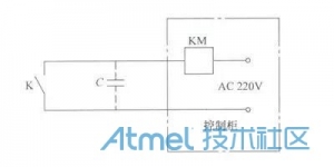
Use the button or PLC switch output to control the start and stop of the remote AC motor (or equipment). The remote switch control failure circuit is shown in Figure 1.

Fault analysis and maintenance method of electrical circuit
Figure 1 Remote switch control failure circuit
It is often found that when you want to turn off the remote AC contactor, you can't turn it off. The reasons are as follows:
Since the switch K is far away from the AC contactor KM, the two wires are long so that their distributed capacitance C will become larger. In the AC circuit, there will be a displacement current flowing through this distributed capacitor. Even if the switch K is disconnected, the KM may not need to be too large to cause the KM to be released, and the device cannot be stopped. In this case, the following solution can be adopted. :
1) It can be remotely controlled with DC signal.
2) On the coil of the AC contactor KM and a lamp or resistor, the current flowing through the distributed capacitor is insufficient to maintain the coil's pull-in.
Field instrument failure analysis
If the process parameters displayed on the display, touch screen and PC screen are outside the normal range, we need to first determine the location of the fault:
1) Measure the input of the controller or PLC to see if the signal input from the field instrument or sensor is normal. If it is normal, it indicates that there is a problem with the input of the PLC or controller (card).
2) If the signal input from the field instrument or sensor is abnormal, the following method can be used to determine the fault location: remove the sensor input signal line, use the standard signal generator to connect to the input of the PLC or controller, and send a standard signal. If the screen still displays If it is not normal, it can be concluded that there is a problem with the input of the PLC or controller (card); if the screen display becomes normal, it can be initially determined as a fault of the field instrument or sensor.
3) If there is no standard signal generator on site, you can also try the normal working instrument to see if the screen display is normal. If it is still not normal, you can conclude that it is a field instrument or sensor failure.
4) Observe whether the wiring of the field instrument or sensor is off. If it does not fall off, use a multimeter to measure the power terminal of the meter to see if there is a voltage signal. If there is no voltage signal, it can be preliminarily determined that the power of the field instrument or sensor has appeared. Problem, further measurement of the power supply, if the power is normal, the power line may be disconnected.
5) If the field instrument or sensor has a power signal, and the process parameters of the production process are also normal, and the output signal of the field instrument or sensor is abnormal, it can be determined that the field instrument or sensor is faulty, replaced or removed for maintenance.
Sensor output signal disorder
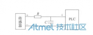
The weak signal of the sensor to the PLC (or other controller) can be reduced by the RC filter. The RC filter is shown in Figure 2.
Fault analysis and maintenance method of electrical circuit

Figure 2 RC filter
The output signal of the sensor, whether it is voltage or current, is filtered by R and C, and the high-frequency interference signal in the signal is filtered out, and the output signal is smoothed. If the sensor is a voltage signal, the resistance R can be larger, from 1kΩ to several hundred kilohms, and the capacitance C is from 0.1 to 10μF. If the sensor outputs a current signal, the sum of the input resistance of the resistor R and the PLC side cannot be greater than the maximum load resistance of the sensor. In most cases, R ≤ 500 Ω, and the value of the capacitor C is 0.11 to 10 μF. When the RC filter is added, the reaction speed of the signal will be slower. For applications where the reaction speed is high (such as fast precision transmission), this cannot be handled.
Fault Analysis of PLC Control Cabinet
Due to the increasingly powerful functions of integrated circuits, the integration of PLC internal boards is already very high, there are few discrete components, and discrete components are mostly micro-sealed devices, so the current PLC or controller maintenance methods are also mainly It is based on replacing the faulty board. The fault analysis method is as follows:
1) If the analog input signal sent to the PLC by the field meter or sensor is normal with a multimeter, and the data on the display is not normal, and the other analog input signals are normal, the input of the PLC or controller may be faulty. .
2) The field instrument or sensor sends the analog input signal of the PLC. The data on the display is not normal. The analog signal input is replaced by the standard signal generator and connected to the PLC. The data on the display is not normal. It can be determined that the input has been burned or the card is damaged, and the input card needs to be replaced.
3) If the PLC or controller program can conclude that there should be an analog output, such as an input analog signal becomes smaller (or larger), an analog output signal should be increased, and the output has no analog signal output, then It may be that the output card is faulty, the output is burned out or the card is damaged, and the output card needs to be replaced.
4) The analog output of the PLC or controller is not normal. The data input function of the display screen outputs a fixed analog signal to the analog output terminal. If the analog output terminal still outputs an abnormality, the output card may be initially determined to be faulty.
5) Switch input signal PLC, but the PLC does not respond or the display is not displayed. You can use the multimeter to measure the input. If the external input signal is normal, you can preliminarily determine that the PLC's digital input card is faulty.
6) The external switch input signal is input to the PLC. The PLC does not respond or the display is not displayed. The input terminal can be removed and the input is high or low. If the switch input signal still does not display normally, then It can be preliminarily determined that the PLC's digital input card is faulty.
7) The PLC switch quantity signal has no output. The switch can be manually triggered by the button on the display. If the switch output signal still has no output, it can be preliminarily determined that the digital output card is faulty.
8) If the program in the PLC is lost (the probability of this failure is low), it is generally the case that all signals cannot be input and output normally, and the program needs to be refilled.
PLC switching input signal is disordered
Sometimes the switching input of PLC or other controller is affected by external interference, and the input error is instantaneous, which causes the PLC to malfunction. At this time, it is eliminated at the input of the PLC with a small capacitor of 0.1μF and a resistor of 1MΩ. Interference such as electrostatic induction or electric field coupling. Eliminate the interference of the digital input as shown in Figure 3. For a +24V active input, the capacitor and resistor are grounded. For a valid 0V input, connect the resistor and capacitor in parallel with +24V.
Fault analysis and maintenance method of electrical circuit

Figure 3 Eliminating interference from digital inputs
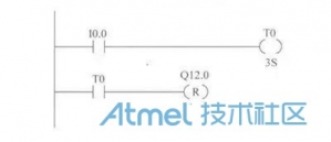
Using the software delay method is also a good anti-interference method. For example, the I0.0 signal is susceptible to interference. The program that controls the Q12.0 reset with I0.0 can use the following anti-interference program. The software anti-jamming program of the digital input is shown in Figure 4.
Fault analysis and maintenance method of electrical circuit

Figure 4 Software anti-jamming program for digital input
In this program, only I0.0 is closed within 3s, Q12.0 is reset, and the interference on I0.0 cannot be maintained for such a long time, so it does not affect Q12.0. In actual use, the time of T0 can be shorter.
Fault analysis of the inverter
1) In the inverter control cabinet, if the motor is in the inverter and power frequency modes, the motor rotates in the opposite direction, it may be that the wiring sequence of the incoming power supply side L1, L2, L3 changes, which is mostly transformer or The electrician side fault maintenance personnel are careless and careless. You can adjust any two power cords on the incoming line side of the inverter cabinet. After the frequency conversion, only changing the wiring sequence of the inverter to the motor will change the rotation direction of the motor. The change of the wiring sequence of the incoming power supply side does not affect the running direction of the motor after the frequency conversion.
2) Frequently, the inverter leakage alarm is faulty. It may be because the cable from the motor to the inverter is too long, or the cable enters the damp area under the well. Because the metal wire inside the cable and the ground at the cable form a distributed capacitance, the frequency conversion The high-frequency harmonics of the device still form a displacement current into the earth, even if the insulated cable is good. At this time, the following measures can be taken: reduce the carrier frequency of the inverter to reduce the displacement current value, increase the output reactor on the output side of the inverter to reduce the high frequency component in the inverter output circuit, and use the harmonic-free frequency conversion on the high-voltage motor. Device.
3) When an overcurrent fault occurs frequently, first check if the load on the motor is too heavy and increase the acceleration time.
4) When there is an overvoltage fault, increase the deceleration time.
5) It is often the case that the motor does not start up. You can try to change the torque boosting parameter of the inverter. In the case of a large static starting resistance, the automatic torque boost is used, and the pump fan can adopt the quadratic torque boosting method.
6) The inverter cabinet often has an over-temperature alarm signal. One reason is that the ambient temperature is too high at room temperature, and air conditioning equipment or ventilation equipment needs to be added. Another reason is that the heat sink on the inverter has dust or flying flocculation process, which needs to be cleaned regularly.
Communication failure analysis
1) If the on-site PLC is working normally and the process parameters in the display have some signal anomalies, the position of the communication fault can be judged based on the position of these signals on the communication bus, and further judge whether the communication module is faulty or the communication bus. malfunction.
2) Many buses with RS-485 hardware protocol as the bus structure, such as MPI, PROFIBUS, CAN, etc., its communication distance can be extended by long distance through fiber or cable. It is necessary to draw everyone's attention that the connection line of each PLC, computer and other devices connected to the bus is not allowed to adopt a method of directly connecting a long distance from the bus directly. The communication bus does not allow the fork connection as shown in Figure 5.
Fault analysis and maintenance method of electrical circuit

Figure 5 Communication bus does not allow forked connections
3) In the case of a repeater, the bifurcation lines of the adjacent two repeaters are not allowed to have a long connection, otherwise the communication will be abnormal. The repeater connection of the communication bus is shown in Figure 6.
Fault analysis and maintenance method of electrical circuit

Figure 6 Repeater connection of the communication bus
4) For the MPI bus, the Siemens manual does not limit the number of operating configuration software PCs, but according to the results of the experiment I have long ago: in the same MPI bus network, there can be no more than 3 configuration software PCs running, up to 3 sets, otherwise PCs that are turned on after they appear will not enter the network.
The video signal on the scene is abnormal.
The large-scale use of frequency converters is very serious for the closed-circuit television monitoring signals of industrial sites. The technicians responsible for CCTV engineering should consider the following measures:
1) Add anti-interference frequency conversion device, modulate the video signal in the field to the interference band of the inverter, so that it is far higher than the interference signal frequency, and then add the demodulator to the receiver to restore the high-frequency signal back. Normal video signal.
2) Reduce the carrier frequency of the inverter to reduce the interference component of the inverter.
Cummins 0-20KW Diesel Generator
Cummins 0-20Kw Diesel Generator,Cummins Portable Power Generator,Cummins Open Type Power Generator,Cummins Container Power Generator
Shanghai Kosta Electric Co., Ltd. , https://www.ksdgenerator.com