The multi-channel pulse amplitude analyzer not only automatically acquires the energy spectrum data, but also obtains the entire energy spectrum in one measurement, thereby greatly reducing the data acquisition time, and at the same time, the measurement accuracy is also significantly improved. Since the 1950s, multi-channel pulse amplitude analyzers have developed rapidly and are now a universal instrument for acquiring nuclear energy spectrum data.
The multi-channel analysis task divides the measured pulse amplitude range into 2n amplitude intervals equally, then measures the number of input pulses in each amplitude interval, and finally obtains the pulse amplitude distribution curve of the input signal. The measurement uses A/D analog-to-digital conversion and data storage technology in computer technology.
A data buffer is opened in the memory of the computer. There are 2n counters in the data buffer, and each pulse amplitude interval has a corresponding counter inside the data buffer. In the multi-channel pulse amplitude analysis, the pulse signal to be analyzed can be sent to the analog-to-digital converter first under the control of the microprocessor, and A/D conversion is performed to form a digital quantity (channel address) representing the pulse amplitude. The digital quantity is then converted by the microprocessor to the corresponding counter address. The content of the counter corresponding to the address is incremented by one (reflecting the track count plus one). Thus, after a period of measurement, the count of each counter in the in-memory counter buffer reflects the amplitude distribution of the input pulse.
1 multi-channel pulse amplitude analyzer structure
A complete nuclear geophysical instrument can usually be divided into two parts: nuclear radiation detectors and embedded systems. Multi-channel pulse amplitude analyzers are a core part of embedded systems. The multi-channel pulse amplitude analyzer collects the signal from the amplifier and performs analog-to-digital conversion on the one hand, and stores the conversion result; on the other hand, the stored conversion result is analyzed by data, and the line is directly displayed, or sent to the computer through a computer interface. Data processing and line display.
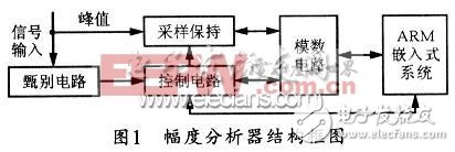
The design block diagram of the multi-channel pulse amplitude analyzer introduced in this paper is shown in Figure 1. When the pulse signal passes through the discriminating circuit and the control circuit, the discriminating circuit gives the pulse over-peak information and starts the A/D conversion. The A/D conversion circuit can perform analog-to-digital conversion on the peak amplitude of the pulse signal, and store the conversion result in the on-chip Flash, and then the corresponding data processing is performed by the microcontroller.

2 multi-channel pulse amplitude analyzer hardware design
2.1 Pulse Linear Main Amplifier
The multi-channel pulse amplitude analyzer consists of a discriminating circuit, a control circuit, a sample-and-hold circuit, an analog-to-digital conversion circuit, and an ARM embedded system, and its control core is an embedded system. Its basic function is to classify the count according to the amplitude of the input pulse. The multi-channel pulse amplitude analyzer divides the range of pulse amplitudes that can be analyzed into a plurality of amplitude intervals. The number of amplitude intervals is the number of channels of the pulse amplitude analyzer, and the width of the amplitude interval is the track width of the pulse amplitude analyzer. The more the number of channels, the finer the amplitude distribution analysis, the corresponding reduction of the counts of each track, the longer the time required for measurement, and the complicated hardware circuits. Therefore, you should not blindly pursue the number of words. It is usually required to have 5 to 10 tracks in the half width of the amplitude peak. For multi-channel spectrometers using NaI detectors, due to their poor energy resolution, 128 to 256 channels are often sufficient to meet measurement requirements. For semiconductor detectors, 1024~8196 channels are required. This article uses a semiconductor detector and uses a 12-bit AD converter, a total of 4096 channels, but in a parallel way to display 1024 channels.
The main amplifier should be placed between the preamplifier circuit and the discriminating circuit, but gain adjustment is required to compensate for changes in the output pulse amplitude of the nuclear radiation detector. Since the amplitude of the pulse signal output by the detector is relatively small (several tens of millivolts to several hundred millivolts), the pulse width is relatively narrow. In order to perform signal amplitude analysis and achieve energy spectrum measurement, it is usually necessary to use a pulse linear amplifier to linearly amplify and pulse shape the pulse signal. For the pulse characteristics, the amplifier is required to have the following technical characteristics:
The first is that the amplification factor should be determined by the amplifier's input pulse amplitude and the required output amplitude. Because the amplitude of the electrical pulse signal of the preamplifier output can generally be adjusted to several hundred millivolts, and the output pulse amplitude of the amplifier is in the range of 1 to 5V, the amplification factor should be about 10 times, considering the signal amplitude of the output of the preamplifier. There are differences, and the magnification should be debuggable.
Followed by the bandwidth of the amplifier. Since the pulse width of the preamplifier output is affected by the relevant circuit, it is usually several μs. Therefore, the bandwidth of the amplifier is required to be 1 to 2 MHz.
The third is the noise of the amplifier. Considering that the amplitude of the signal from the preamplifier is relatively small, the input noise of the selected amplifier should be as small as possible. In general, the use of low-noise op amp components can effectively reduce the inherent noise inside the circuit.
In addition, input impedance such as amplifier, anti-counting overload, amplifier stability, power consumption, etc. should also be considered in circuit design and debugging. Since the alpha pulse signal has a pulse width of about 1 to 2 microseconds after being shaped, the gamma pulse signal has a pulse width of about 3 to 5 microseconds after being shaped. Therefore, when an operational amplifier is selected, an operational amplifier should be considered. Conversion speed. The operating amplifier of this system uses CA3140, which has the characteristics of high input impedance, low noise, low power consumption and small temperature drift.
2.2 Peak detection circuit
The peak detection circuit is composed of a discriminating circuit and a control circuit. The function of the discriminating circuit is to detect the signal timing, and the control circuit controls the analog switch and the ADC conversion according to the timing of the discriminating circuit. The control circuit must be strictly combined with the timing of the discriminating circuit to complete the peak detection task.
Since the amplitude of the pulse signal output by the nuclear radiation detector is proportional to the energy of the incident particles, the energy of the radiation can be known by measuring the amplitude of these pulses. It can be seen that pulse amplitude measurement technology is an important issue in nuclear energy spectrum measurement. The discriminating circuit needs to solve three signal-related information: one is the information exceeding the threshold signal; the other is the over-peak time information, that is, the time information for starting the ADC conversion; and the third is the time information that the ADC completes the conversion. There are also three key issues in the screening circuit, which should be noted in the study:
First, since the alpha and gamma ray pulse widths of the amplifier output are relatively narrow (about 1 μs to 5 μs), and the ADC conversion speed used in this system is 10 μs, the peak value of the pulse signal peak is broadened. The sample-and-hold circuit requires a fast sampling rate so that the hold time can reach the ADC sampling time specification.
Secondly, due to the randomness of the pulse signal, in order to prevent the signal from being over-densified, the system uses a 10μs conversion speed ADC. Therefore, theoretically, if the two signals are separated by 10μs, the leakage will be caused. . Due to problems such as CPU processing speed, in fact, this time interval may be 3 to 10 times longer, that is, between 30 and 100 μs (depending on CPU processing speed and code size), or even more, that is, There is very little chance that this will happen to the actual signal, so this problem can be ignored.
In addition, the amplitude signal error record caused by the signal over-density is also solved, and the signal of the high-energy region may be misinterpreted as the signal of the low-energy region, which may easily cause the problem that the low-energy count is too large and the high-energy count is small.
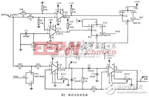
Figure 2 shows the schematic of the discriminating circuit and the control circuit. The main function of the discriminating circuit is to complete the over-peak detection and remove the signal noise. The noise of the signal whose energy is less than the threshold can be set by setting the closed value. After the peak is passed, information is provided to the control circuit; the main function of the control circuit is to complete the control of the A/D read/convert state. The control circuit can be constructed by a 74HC74 trigger.

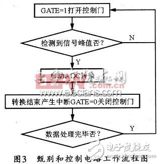
The specific working process of the screening and control circuit is that the embedded microprocessor control center sends a signal to the control circuit to make the control circuit be in working state. When the pulse signal reaches the multi-channel pulse amplitude analyzer, the discriminating circuit discriminates, and After the peak value is over, the time information of the peak pass is supplied to the control circuit; after that, the analog circuit is started by the control circuit, the digital-to-analog conversion is completed, and the interrupt is generated by the embedded microprocessor control center, and the control circuit is stopped at the same time. Corresponding data processing; after the interrupt is completed, the MCU sends a signal to make the control circuit work again.
At the beginning of sampling, the ARM starts the A/D by controlling the 74HC74. Then, the RD and SD terminals of U2A and U2B are output high, and the control circuit is in the state of receiving signals. When the energy of the rising edge of the signal is lower than the set closed-value voltage, the CLK terminal of U2A is low voltage. At this time, the RD and SD terminals of U2A are both high, and the output pin 5 remains at the original low level. change. When the energy of the rising edge of the signal is higher than the set closed voltage value, the CLK terminal of U2A is high voltage, and the output terminal 5 outputs a high level to start U2B. When the pulse does not reach the peak value, the voltage of the non-inverting input terminal of the comparator U1B is lower than the voltage of the inverting input terminal, and the output voltage of the 6 terminal is low. When the peak is over, the 6 terminal outputs a high level, and the R/C output low level to start. A/D conversion. After the conversion is completed, the ARM re-controls the A/D to acquire the next pulse signal. The workflow of the discriminating circuit and the control circuit is shown in Figure 3.

2.3 analog to digital conversion circuit
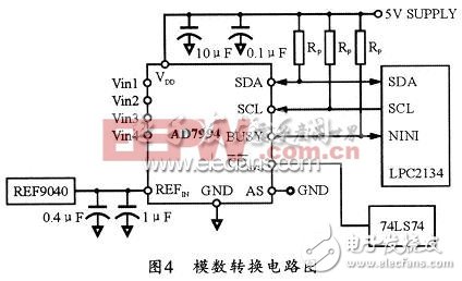
The function of the analog-to-digital conversion circuit is to convert the analog quantity into a digital quantity and feed back the conversion result to the microcontroller. The multi-channel pulse amplitude analyzer is mainly used to quickly and accurately sample the input nuclear pulse signal and convert the amplitude value of the pulse into a digital quantity that the microcontroller can process. The analog-to-digital conversion circuit is a key component of the multi-channel pulse amplitude analyzer. Its performance directly affects the energy resolution and conversion accuracy of the whole system. Considering the main performances of the ADC chip of multi-channel pulse amplitude analyzer (such as conversion speed, power consumption, conversion accuracy), etc., this system selects AD7994 of AD company, and adopts the method of “conjunction†in practical work. If the 4 lanes are made for 1 channel, the width of the channel can be reduced to 1/4 of the original. This approach reduces nonlinear errors due to the ADC itself. The specific circuit design is shown in Figure 4.

TPS Flat Cable
AS/NZS 5000.2 approved eletric cable: TPS,building cable export to Australia, New Zealand, Fiji, Papua New Guinea and other Oceania market for more than 10 years, quality assured.
- Standard applied: AS/NZS 5000.2
- U0/U: 450/750V
- Certification: SAA
- fire resistance or Low smoking and Halogen free or other property can be available
Tps Flat Cable,Tps Flat Wires,Tps Flat Electrical Cable,Rubber Electrical Cable
Shenzhen Bendakang Cables Holding Co., Ltd , https://www.bdkcables.com