Without adjusting the volume, the user must either set the volume too high to distort the dynamic peak; or set the volume too low, thereby affecting the quality of the conversation. For laptops with small speakers, this problem may cause users to hardly watch DVDs.
Automatic level control theory Amplifiers with automatic level control (ALC) can help solve problems caused by small speakers. Although the amplifier itself cannot increase its maximum output voltage without increasing the operating voltage, and cannot increase the power of the small speaker, it can dynamically adjust the effective value of the output voltage when playing audio. If the peak of the audio waveform (above a predefined threshold) is reduced to a level that more closely matches the rest of the audio signal, then the volume of the entire signal can be increased without clipping distortion of the peak. This is commonly referred to as compression or limiter based on compression ratio, these technologies have been very mature in the entire audio industry.
When the signal is above the compression threshold, a small compression ratio (for example, 2: 1) will reduce the 4dB increment at the input to 2dB at the output. Larger compression ratios (20: 1 or greater) are classified as limiting, because once this threshold is reached, the output waveform will maintain a fixed amplitude regardless of how the input signal increases. Compression generally works on recording and mixing levels, but it can also work on audio data streams.
For example, the MAX9756 amplifier, its automatic level control (ALC) is basically like a limiter. When it detects that the output signal exceeds the set threshold, it will reduce the gain and keep the output below the threshold. The gain response of the MAX9756 above the threshold is nearly flat, and the compression ratio is almost infinite (Figure 1).
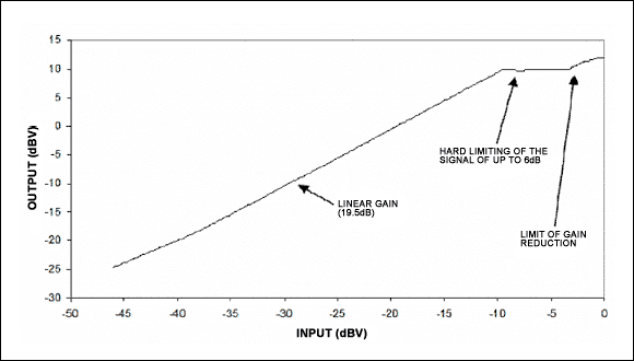
Figure 1. For low-level volume, the amplifier is like a normal linear amplifier; when the volume exceeds the threshold, the gain is reduced to avoid the output exceeding the threshold. When the output voltage increases above the threshold, the maximum gain attenuation is limited to 6dB.
The response speed of the automatic level control (ALC) timing limiter to changes in signal amplitude can significantly affect the sound effect. When the output signal exceeds the threshold, the speed of gain attenuation is expressed in response time. Subsequently, the gain will remain at the attenuated level until the signal amplitude drops below the threshold. The release time indicates how quickly the amplifier returns the gain to its original value. The response time of the amplifier MAX9756 is determined by the capacitance connected between the CT pin and ground. The following formula can be derived from the capacitance value to start time:

The release time is calculated in proportion to the response time and adjusted by the voltage applied to the DR pin. By connecting the DR pin to VDD, VBIAS or GND, one of three ratios can be selected. The MAX9756 adds a fixed hold time of 50ms to all release times, and the gain does not change during the hold time.
Figure 2 shows the effect of bursting a large amplitude pulse on a small amplitude signal. As the gain drops sharply, the amplitude of the large signal pulse is significantly attenuated on the output waveform. The voltage controlling the gain reduction in the figure is the voltage of the external capacitor of the CT pin, and the response time is set by the capacitor. The control voltage is proportional to the gain attenuation (dB) within a specified time.
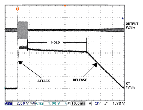
Figure 2. A brief large signal is applied to observe the complete process of automatic level control ALC. The hold time of the MAX9756 amplifier is 50ms, and the response and release time can be adjusted by external components.
The length of the response and release time must meet the characteristics of the sound source and the sound effect requirements. The shorter time constant allows the automatic level control to respond quickly to changes in signal amplitude, and even if very short signal spikes occur, it can provide effective protection. Ensure that the loudspeaker is not damaged under a large signal, but when the gain is quickly adjusted according to the dynamic change of the signal, a "popping" or "gasping" sound may be generated.
For a film soundtrack that continuously changes the amplitude of the signal, using a longer time constant can avoid noise and optimize audio quality. In this case, the gain remains relatively fixed when the signal strength changes rapidly, and only the long-term high-intensity signal is adjusted for gain to give the amplifier sufficient response time. Loudspeaker protection is still effective because automatic level control (ALC) reduces most of the signal amplitude that may cause damage.
By monitoring the gain attenuation control voltage and signal waveform (Figure 3), the effects of longer and shorter response and release times can be observed. In order to generate a representative waveform, the input signal uses a full-volume audio signal. In waveforms where the overall signal strength is relatively constant, shorter response and release times will cause frequent gain adjustments. The longer response and release time maintain a smooth gain response to avoid the amplifier responding too fast, thereby maintaining the amplitude of the entire signal while basically retaining the dynamic range.
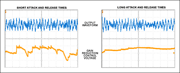
Figure 3. Short response and release time (a) cause frequent changes in gain adjustment, which may reduce acoustics. The long response and release time (b) produce a smooth gain response.
The threshold of automatic level control (ALC) The speaker amplifier in notebook computers generally works under 5V power supply. With an 8Ω speaker, the maximum continuous power that can be theoretically provided in a bridged load (BTL) configuration is:
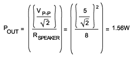
Based on the 5V operating voltage, when the input amplitude is higher than the corresponding value of the maximum POUT, clipping will occur. The MAX9756 amplifier can adjust the gain attenuation threshold by selecting a resistor between PREF and ground (MAX9756 injects a constant current of 12µA into this resistor). This resistance value can be calculated by the following equation (here the 1.4W threshold is taken as an example):

By adjusting the RPREF value to change the threshold, if the audio system is limited by the power capacity of the speaker, you can set the threshold so that it is far below the maximum output power of the amplifier to ensure that the power capacity of the speaker is not exceeded. If the speaker can withstand the full output power of the amplifier, set the threshold just below the limiting level to optimize sound quality and avoid the speaker from being damaged by long-term strong changing signals. Clipping not only sounds bad, it can even cause permanent damage to the speakers. It is difficult for the mechanical components of the speaker to recover the steep edge of the clipped signal, and it will cause failure after a long time.
Figure 4 shows the effect when the threshold is set just below the maximum output power of the amplifier. The input signal is a sine wave with high and low amplitudes interleaved. The output waveform is obviously clipped during the response time, but when the gain reduction is completed, the clipping phenomenon can be avoided.
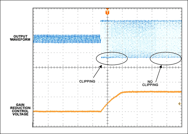
Figure 4. During the transition from a small signal to a large signal, the output waveform initially experiences clipping distortion, but when the gain is attenuated, the output waveform returns to the desired sine wave state.
Lowering the compression ratio The limiting function provided by the MAX9756 helps protect the speaker and avoid clipping, but when automatic level control (ALC) is effective, it will completely eliminate dynamic changes. The infinite compression ratio means that when the input signal increases, it has no effect on the output, resulting in a dynamic, monotonous audio effect. If strict control of the output waveform is not required, a lower compression ratio can maintain a certain dynamic change while avoiding clipping. A lower compression ratio will reduce the dynamic range of the audio signal, but it is not completely eliminated. Through the peripheral circuit of Figure 5, MAX9756 can get a lower compression ratio.
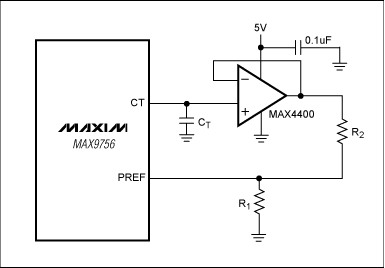
Figure 5. The MAX9756 plus a MAX4400 operational amplifier and resistor (R2) can reduce the ALC compression ratio.
The MAX4400 op amp buffers the CT output of the MAX9756 to ensure that the external circuit does not affect the CT voltage and therefore the release time. The typical input impedance of the MAX4400 is 1000GΩ, which eliminates leakage current that may discharge the capacitor in advance. The output of the operational amplifier is fed back to PREF through R2. The R1 and R2 voltage dividers determine the new automatic level control ALC threshold. The specific threshold is determined by the following formula:

Before reaching the threshold, the equivalent impedance of pin PREF is the parallel connection of R1 and R2, because both resistors are connected to ground at the same time. Therefore, setting these two parallel resistors in this configuration sets the automatic level control ALC threshold. The right side of the equation is the previously mentioned RPREF calculation formula, and the left side of the equation is the parallel resistance of R1 and R2.
The ratio of R2 to R1 determines the compression ratio. When R2 is much larger than R1, the automatic level control ALC has a high compression ratio similar to the MAX9756 standard hard limit configuration. When R2 is less than R1, ALC has a low compression ratio and maintains most of the original dynamic range in the audio signal. To get a 3: 1 compression ratio, let R2 be 2.5 times R1. Figure 6 shows the MAX9756 standard limiting configuration and the voltage gain effect when R2 / R1 = 2.5.
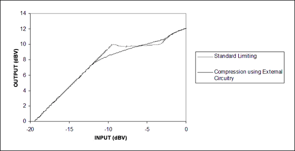
Figure 6. Compared with the MAX9756 standard limiting configuration, it can achieve a smooth gain adjustment with external circuits.
Automatic level control (ALC) improves performance The performance improvement brought by automatic level control (ALC) is very obvious (Figure 7). Figure (a) shows the output waveform when there is a strong sound in the DVD signal without automatic level control (ALC); Figure (b) shows the automatic level control (ALC) under the same input and the same volume setting Working results.
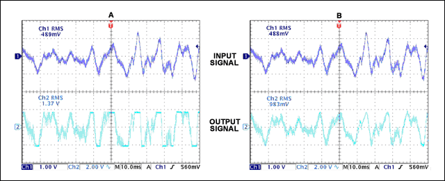
Figure 7. (a) Without ALC, a strong input signal causes severe clipping of the output; (b) Under the same input waveform, when ALC is working, the output waveform has no clipping distortion.
The user can turn up the volume to improve the dialogue effect, and there is no need to worry about the appearance of other strong sound signals. The sound quality will also be improved by avoiding clipping. In addition, automatic level control (ALC) extends the life of the speaker (reduces clipping) and helps protect low-power speakers. The maximum volume setting is 6dB higher than the equivalent system without ALC.
Automatic level control (ALC) can also be implemented digitally, or by existing DSP hardware; complex and sophisticated processing procedures such as multi-band compression can be used to further improve sound quality and enhance speaker protection. But this kind of scheme makes ALC in the digital domain a huge DSP system, requiring more calculation cycles and greater power consumption. On the other hand, for laptops and handheld DVD players with demanding battery life, it is a good compromise to integrate analog ALC in the speaker amplifier.
PanelView Plus 6 Graphic Terminals
Our Bulletin 2711P PanelView™ Plus 6 Graphic Terminals let you monitor, control, and display application status information graphically. These terminals offer the open-platform flexibility of the Windows® CE operating system. They are available in 4-15 in. standard display sizes. FactoryTalk® View Studio Machine Edition software lets you program all of your PanelView Plus 6 graphic terminals.
Features
-
Provides significant improvements over the PanelViewâ„¢ Plus 400 graphic terminals
- Processor speed increased from 350 MHz to 1 GHz
- Screen transition rate is up to 70% faster
- System memory increased from 64MB RAM to 256MB RAM
- Flash storage space increased from 64MB to 512MB
- Includes 80MB nonvolatile storage for applications
- Increased illumination of LED backlight displays
- Greater connectivity to a variety of peripherals such as printers, mice, and keyboards
- Supports ActiveX® Controls
- Integrates with third-party software such as Microsoft® Internet Explorer® and Microsoft Office Viewers
- Supports remote connectivity (VNC and FTP)
- Offers backup restore functionality
- Provides remote recipe and data management through .CSV files
- Uses vector-based graphics from Symbol Factory
- Includes built-in PDF viewer for context-sensitive operator support
- Supports DataStore Plus logging and trending, which eliminates the 300,000 data point limit
PanelView Plus 6 400 Graphic Terminals
- Includes a 4 in. flat-panel color display with 320 x 240 resolution and 18-bit graphics
PanelView Plus 6 600 Graphic Terminals
- Includes a 6 in. flat-panel color display with 320 x 240 resolution and 18-bit graphics
PanelView Plus 6 700 Graphic Terminals
- Includes a 6.5 in. flat-panel color display with 640 x 480 resolution (minimum) and 18-bit graphics
- Supports operator input via keypad (22 funtion keys), via touch screen or via keypad and touch screen
PanelView Plus 6 1000 Graphic Terminals
- Includes a 10.4 in. flat-panel color display with 640 x 480 resolution (minimum) and 18-bit graphics
- Supports operator input via keypad (32 function keys), via touch screen or via keypad and touch screen
PanelView Plus 6 1250 Graphic Terminals
- Includes a 12.1 in. flat-panel color display with 800 x 600 resolution (mimimum) and 18-bit graphics
- Supports operator input via keypad (40 function keys), via touch screen or via keypad and touch screen
PanelView Plus 6 1500 Graphic Terminals
- Includes a 15 in. flat-panel color display with 1024 x 768 resolution (minimm) and 18-bit graphics
- Supports operator input via keypad (40 function keys), via touch screen or via keypad and touch screen
AB PanelView Modules,Terminal Touch Screen,Grayscale Terminal Keypad,Display Module Panel View
Xiamen The Anaswers Trade Co,.LTD , https://www.answersplc.com