Abstract: Aiming at the current traffic situation, this paper proposes a scheme design of intelligent bus stop sign display system using wireless technology. The system consists of a wireless transmission module, an information processing module and an information display module, and realizes an intelligent bus stop sign display system capable of displaying and feedbacking real-time bus status, location information, and emergency information. Among them, the wireless transmission module applies SIM300-GPRS module, which is mainly responsible for transmitting and receiving the required data information; with the powerful computing power of the STM32 main control chip, the information processing module calculates the existing data by modeling and algorithm correction. The basic information such as the location and status of the bus to the station is updated in real time; the information display module is responsible for transmitting information such as bus status, emergency events, and public service advertisements to the passengers through the LED screen, and is responsible for displaying and scheduling various information. Based on the above ideas, the design of the intelligent bus stop sign display system has been completed.
This article refers to the address: http://
In recent years, China's economy has made tremendous progress, and the rapid development of the city's economy has led to the rapid development of the domestic bus industry. During this period, the state has introduced many preferential policies for the bus industry. With these powerful impetus, the electronic informationization and intelligence of the bus industry have been promoted. The pace has been accelerated, and no-sale tickets have been operated in many cities in China, and IC card charging methods have become popular in large and medium-sized cities in China. With the development of the bus industry and the growth of the masses of consumers by public transportation, consumers have made more convenient and intelligent requirements for the existing public transportation system in order to better understand the public transportation information and achieve the purpose of facilitating travel. Based on these requirements, this design proposes a smart bus stop sign display system scheme based on wireless transmission information, which can display the status of the bus status and emergency information in real time, and provide passengers with comprehensive information for convenient travel. Traffic lines give less traffic pressure and safety hazards to urban traffic. The intelligent public transport system greatly facilitates passengers to choose a course of action, evacuate traffic flow, guide the entire traffic situation to an ideal state, make traffic smooth and safe, improve the efficiency of road use, and add a beautiful color to the beautiful city. Landscape.
1 Intelligent public transport system
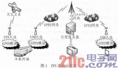
The Intelligent Transport System (ITS) is mainly divided into three parts, namely the bus vehicle monitoring center, the vehicle terminal and the electronic station card. The working principle of the system is shown in Figure 1.

The vehicle terminal transmits information such as the real-time location of the bus and the number of in-vehicles to the bus monitoring center through the wireless communication network, and plays the role of data collection, which is the basis of the whole bus system.
The monitoring center performs comprehensive processing according to the data transmitted from the vehicle, and sends the data processing result to the corresponding electronic station card through the wireless communication network, and at the same time, collects feedback information of each public transportation display system, for objective factors and emergencies. The resulting bus dispatch situation is handled to achieve the optimal purpose of reducing traffic pressure and saving resources;
The electronic station card is responsible for receiving the data information, and calculating the information of the bus that is about to arrive through the close combination of the internal modules of the system, and is released by the display device such as the LED dot matrix screen to provide information services for the passengers waiting for the bus. Moreover, this part is also responsible for the display of information such as emergency situations and public service advertisements, so as to facilitate the citizens to travel safely and travel in a civilized manner.
2 system design
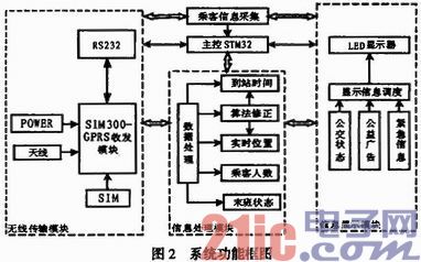
The electronic station display system is an important part of the Intelligent Transportation System (ITS) and the key and foundation of the ITS. The functional block diagram of the intelligent bus stop sign display system design scheme is shown in Figure 2. It mainly includes main control, passenger information collection, SIM300 wireless transceiver, data processing and information display.

In this system, the wireless transmission module mainly uses GPRS technology to realize data transmission with the control center and the vehicle terminal. The received data is decoded and transmitted to the information processing part. The data is processed in the information processing module, and the mathematical model and objective correction factor are established. Finally, the location information of the bus at the moment and the calculated arrival time are obtained, and basic information such as the real-time bus status such as the number of passengers and the last shift state is obtained, and finally updated to the information display module and displayed. The display scheduling module displays the basic status information of the upcoming public transportation in real time, but after a certain period of time, by adjusting the objective factors such as the number of passengers, emergency information, and public service advertisements, the display content is adjusted to achieve better service for passengers. . The passenger information collection module collects basic information such as waiting passenger information such as the route, the number of passengers waiting for each bus, and feeds back to the monitoring center through the data transmission module to achieve more optimized bus scheduling. The modules work in coordination with each other to realize a smart bus stop sign display system that facilitates the convenience, safety and civilized travel of the citizens.
3 system hardware design
The system mainly controls the wireless information transmission part, the information processing and the display part by the main control chip, and finally displays the travel information to the passenger through the LED. The information processing and information display scheduling are all completed by the STM32 main control chip, and the data processing and display are completed through certain algorithms and real-time feedback information. The wireless module is connected to the STM32 main control chip by the SIM300 module and the peripheral circuit, and the initialization and data transmission, encoding and decoding are completed under the control of the main control. The LED part drives the 74HC595 and 74HC138 chips by means of the main control chip to realize the LED dot matrix control and display function.
1) The main controller main controller selects STM32F103VE enhanced single-chip microcomputer, STM32 series single-chip microcomputer uses high-performance ARM CortexTM-M3 32-bit RISC core, working frequency is 72MHz, built-in high-speed memory (up to 512K bytes of flash memory and 64K bytes) SRAM), with powerful information processing capabilities, rich I/O ports and peripherals connected to two APB buses, is designed by STMicroelectronics for high performance, low cost, low power embedded applications The product. In this design, STM32 connects SIM300 wireless transceiver module through serial port to realize data transmission and module control. The LED is connected to the STM32 via the SPI interface emulated by the GPIO port to complete the information display.
In this design, the main function of the STM32 is to control the wireless transmission module to receive vehicle status information, process the data, and send the processed information to the wireless transceiver module SIM300 for feedback back to the monitoring and display on the LED dot matrix screen. In addition, STM32 also completes the initialization of chips such as SIM300 and LED dot matrix.
2) The wireless transceiver module SIM300 is a GSM/GPRS tri-band/quad-band module introduced by SIMCOM, which provides a wireless interface for voice transmission, short message and data services. The SIM300 integrates a complete RF circuit and a GSM baseband processor, and is suitable for developing some GSM/GPRS wireless applications, such as mobile phones, wireless data transmission services, remote measurement, etc., and has a wide range of applications. The focus of this design is mainly the serial communication between the single-chip microcomputer and the SIM300 module, and the transmission and reception of wireless GPRS data.
3) The LED display is expanded by P3.75's 8 x 8 monochrome dot matrix module, with 128/8=16 horizontal and 64/8=8 vertical. In order to facilitate the design of the circuit board, it is first expanded from 4 horizontal blocks to 32 x 32 display units, and then 8 32 x 32 units are designed. The row driver control chip selects 74HC138D, the power chip selects 4953, and the column drive control chip adopts 74HC 595D. The display control card uses the STM32F103VBT6 MCU from STMicroelectronics as the main control chip. The STM32F103VBT6 itself has 128KB of on-chip flash and 64KB of on-chip RAM, which is enough to store the program code, so there is no need to expand the external ROM and RAM. The chip GT23L32S4W supports up to 22 fonts, greatly enhancing the display capabilities of characters. At the same time, the control card adopts RS232/485 communication interface, which can display and display the display conveniently through RS232/485. It is thus easy to realize real-time display and update of bus status information.
4 system software design
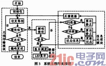
After the system is powered on, the SIM300 module, LED display, SD card and system peripherals are initialized. The system peripherals mainly include system clock, timer, GPIO port, interrupt, SPI and USART. The MCU reads the data received by the SIM300 wireless transceiver module through the USART interface, and then decodes the data according to the protocol, and matches the decoded data with the system information of the station card pre-stored in the SD card, and the matching is successful. The specific information is displayed on the LED screen. The main program flow chart of the system is shown in Figure 3. According to the data flow direction, it is mainly divided into three parts: data transmission, data processing and data display. The emergency information needs to be displayed in the display part immediately. The process is data reception and data processing. Module, the data is corrected by the algorithm and then fed back to the monitoring center and the bus status data is updated. It mainly includes the location information of the vehicle, emergency information, pre-arrival time, and so on.

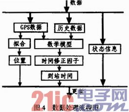
The information processing part, by means of the powerful computing power of the main control chip STM32 and the clock of up to 72MHz, first classifies the received data except the emergency information as follows: GPS information, bus arrival time history data, pre-arrival status information Etc., wherein the emergency information is sent directly to the display module without being processed by the information. Its data processing flow chart is shown in Figure 4. Due to the limitation of GPRS transmission speed and traffic cost, the data cannot be continuously refreshed. Therefore, the GPS information is processed by the quadratic curve fitting method in the mathematical model to realize the real-time and continuous display of the bus position; GPS The information and historical data are combined with each other, and the real-time speed simulation model of the vehicle is used to obtain the arrival time of the pre-arrived bus, but there are other objective factors such as the morning and evening peaks, the change of the festival, etc., so the objective correction factor is corrected on this data, so that The data is more realistic, and the actual measured objective correction factor improves the accuracy of the predicted arrival time by 27.3%. The status information is directly updated to the display module after being compared with the historical data. At this point, the information processing module provides the optimal pre-arrival status and location information for the display module.

5 Conclusion
The design of the intelligent electronic station sign based on GPRS proposed by this design realizes the real-time display of the real-time operation of the bus and the intelligent display of the bus stop information. At the same time, the emergency situation and the display of public service advertisements have made outstanding contributions to improving the personal safety and spiritual civilization construction of citizens. Greatly improve the efficiency of public transportation management and realize the intelligence and informationization of the urban public transportation system. The system has excellent reliability and stability, and provides an effective way for improving urban public transportation management and improving public transportation resource sharing. At the same time, using CPRS wireless technology as a means of information transmission, bus stop management can be realized more simply and conveniently. And can update the information such as advertising data in the system in time. The intelligent bus stop sign display system brings great convenience to the citizens and has long-term development prospects.
- STM32 microcontroller Chinese official website
- STM32 microcontroller official development tools
- STM32 microcontroller reference design
Ei 96 Transformer,96 Va Transformer,Ac Current Transformer,Ei Transformer
Guang Er Zhong(Zhaoqing)Electronics Co., Ltd , https://www.cnadaptor.com