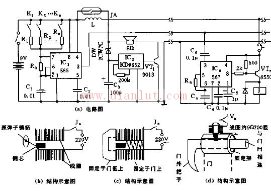
As shown, the electronic lock device includes control circuitry and audio circuitry placed at the hotel service desk, and receiving and operating circuitry placed in each room. It consists of a control, audio circuit and multiple parallel receiving and operating circuits. The control circuit is composed of IC1 (555) and R1 ~ Rn, R0, Cl, and generates various oscillating frequency signals in the range of 10 Hz to 500 kHz, and the receiving circuits of different frequencies are placed in each passenger room. When one of the self-locking switches K1 to Kn is closed, the corresponding Kn in the room is pressed by the passenger when the door is opened, and the door is opened. At the same time, due to the current flowing in the coil L, the reed pipe is sucked, and the circuit composed of IC2 (KD9562) emits an audible sound to inform the service desk that the door has been opened, and the main switch K can be turned off. The receiving and operating circuit of the passenger room is composed of a dedicated audio decoding circuit 567 and a transistor switching relay controller. The center frequency of the decoding circuit of each room corresponds to the 555 vibration frequency determined by the service stations K1 to Kn. 567 is an audio decoding circuit with a locked loop. When the center frequency is met, the 8 feet of the 567 circuit are turned into a low electric dry, the VTn is turned on, the J is pulled, the magnetic coil is actuated, and the guest rotates the lock at the same time, that is, the door opened. 567 The center frequency of the decoding boundary is fo = 1 / 1.1 RnCn. The center frequency of the decoder of each room is in one-to-one correspondence with the different oscillation frequencies of the originating end. Figure (b) is a schematic view of the structure modified by the original marble lock. When the relay is pulled in, the marble lock steel core is sucked into the middle part, thereby pulling the lock handle and the switch; Figures (c) and (d) are directly used as the door bolt by the steel core, and Figure (c) is used for AC 220V. ) Use DC 9V.
4.14 Mm Wrie To Board Connectors
4.14 mm Wrie To Board Connectors
4.14 mm Wrie To Board Connectors
ShenZhen Antenk Electronics Co,Ltd , https://www.antenksocket.com