Today's cars are at the junction of electronic systems, minimizing the adoption of mechanical systems and becoming the largest and most expensive "digital tool" in people's lives. Due to availability and environmental reasons, as well as the need to improve the safety of internal combustion, hybrid and all-electric vehicles, the market has gradually reduced its dependence on gasoline, which is the driving force for the “digital†transformation.
In the case of electric vehicles, it is crucial to be able to monitor the power consumption of the car in real time and accurately.
Several ways to monitor and control power consumption
To monitor the power consumption of an electronic system, it is necessary to continuously measure current and voltage. The voltage can be measured directly using an analog-to-digital converter (ADC). If the ADC input range is less than the monitored voltage, then a resistor divider (Figure 1) may be required.
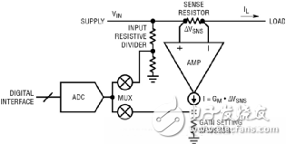
Figure 1: Measuring input voltage and load current on the rail (detection voltage)
To measure the current, a sense resistor is placed in the power path and the voltage drop is measured. As shown in Figure 1, the transconductance amplifier converts the high side detection voltage into a current output that flows through the gain setting resistor to produce a ground-referenced voltage that is proportional to the load current and suitable for feeding to the ADC.
To minimize power consumption, the full scale detection voltage is limited to tens of millivolts. Therefore, the amplifier input offset needs to be less than 100μV.
To calculate power, a microcontroller or processor that accesses ADC data through the ADC's digital interface must be used to multiply the voltage and current readings. To monitor energy consumption, it is necessary to accumulate (add) power readings over time.
In order to switch the power supply, an electromechanical relay is generally used in the automotive circuit.
To save space, solid-state switches such as N-channel and P-channel MOSFETs are used instead of relays, resulting in a PCB design where all components are on the same board and can be assembled using a reflow process. The P-channel MOSFET is turned on by pulling its gate-level low and is turned off by connecting the gate to the input voltage. Compared to N-channel MOSFETs, P-channel MOSFETs are more expensive when the on-resistance is the same, and their choice is narrow, limited to larger current values ​​(above 10A). N-channel MOSFETs are the best choice for handling large currents, but require a charge pump to increase the gate voltage above the input voltage. For example, a 12V input requires a 22V gate voltage, ie the MOSFET gate is higher than the input 10V. Figure 2 shows the implementation of a power switch circuit.
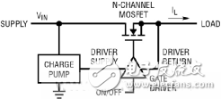
Figure 2: Power rail on/off with N-channel MOSFET
Common power buses also need to provide protection against short-circuit and overload faults, which can occur in any board or module. To implement the circuit breaker function, the output of the amplifier in Figure 1 and an overcurrent threshold can be compared to turn off the gate driver in Figure 2. This solution replaces the fuse because the fuse reacts slowly, the tolerance is too wide, and it needs to be replaced after the fuse. To save board space, it is desirable to have an integrated solution when switching, protecting and monitoring power flow in the automotive power bus.
Integrated power control and telemetry solutionsThe LTC4282 is a hot-swappable controller and circuit breaker that provides energy telemetry and EEPROM (Figure 3), and meets the needs of high current applications with innovative dual current path features. By controlling the external N-channel MOSFET, the controller smoothly powers the bulk capacitor to avoid input power disturbances and currents reaching destructive levels, thus ensuring that the power supply is safely turned "on" and "off" from 2.9V to 33V. open. The LTC4282 is located at the entrance to the board's power supply and has a 0.7% accuracy 12- or 16-bit ADC reporting board voltage, current, power and power through an I2C/SMBus digital interface. The internal EEPROM provides non-volatile storage for register settings and fault log data, speeding up debug and failure analysis during development and in the field.
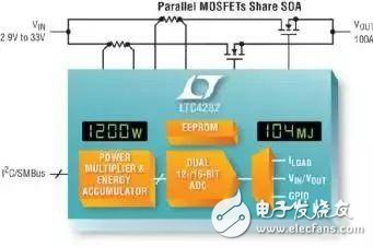
Figure 3: LTC4282 Circuit Breaker with Power/Energy Telemetry and EEPROM
The LTC4282 has a 2% accuracy current limit circuit breaker that minimizes overcurrent design, which is even more important at high power. In the event of an overcurrent condition, the LTC4282 folds back the current limit to maintain constant MOSFET power consumption during the adjustable timeout period. After the timer expires, the circuit breaker disconnects the faulty module from the utility power bus. The idle module can also disconnect from the power bus to save power. The digitally configured circuit breaker threshold allows for dynamic adjustments as the load changes, facilitating the selection of small resistance value sense resistors. The minimum and maximum values ​​of the monitored electrical parameters are recorded. When the 8-bit adjustable threshold is exceeded, an alert signal is issued. To prevent catastrophic damage to the board, these MOSFETs are continuously monitored to detect anomalies such as low gate voltage and drain-source shorts or large dropouts.
SOA shared path
Although the LTC4282 controls a single power supply, it provides two parallel current limit paths for the load current. High-current boards with traditional single-channel controllers use multiple MOSFETs in parallel to reduce on-resistance, but all of these MOSFETs require a large safe operating area (SOA) to withstand overcurrent faults because it cannot be assumed Parallel MOSFETs share current during current limiting.
In addition, the choice of MOSFET narrows at higher current levels, the price goes higher, and the level of SOA does not keep up with the RDS(ON) drop. By separating the current into two precisely matched current-limited paths, the LTC4282 ensures that both sets of MOSFETs will share current even under overload conditions. For 100A applications, each path has a design current limit of 50A, which reduces SOA requirements by half, broadens the choice of MOSFETs, and reduces their cost. This is called a “match†or “parallel†configuration because the two paths are designed with similar MOSFETs and sense resistors.
In addition, the LTC4282's dual current path is also used to decouple the MOSFET SOA from the on-resistance. Large SOAs are important for situations where surges, current limits, and input voltage steps are stressful. When the MOSFET gate is fully turned on, the low on-resistance reduces voltage drop and power loss during normal operation. However, these are conflicting requirements because MOSFET SOA typically degrades as the on-resistance improves. The LTC4282 allows the use of one path with one MOSFET that can handle stress conditions and another path with low on-resistance MOSFETs. This is known as a hierarchical start configuration.
In general, the stress processing path is turned on during startup, current limiting, and input voltage steps, while the RDS(ON) path remains off. The RDS(ON) path is turned on during normal operation to bypass the stress path, providing a low on-resistance path for the load current, reducing voltage drop and power loss. Depending on the magnitude of the MOSFET stress at startup, there are two graded start configurations, low stress (Figure 4) and high stress.
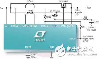
Figure 4a: Low stress graded start configuration provides the lowest cost for applications >50A
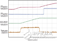
Figure 4b: Startup with a low stress grading start configuration: GATE1 is first turned on to trickle charge the output (with a low surge current level of 2A). GATE2 turns on when SOURCE (output) goes above the power good threshold.
High stress grading start configurations are recommended for application current levels below 50A, while parallel and low stress grading start configurations are recommended for applications above 50A. The lowest MOSFET cost compared to a single-path design is provided by a low-stress grading start configuration at the expense of uninterrupted operation under transient conditions and the inability to start with load current. The parallel and high stress grading start configuration initiates a load and provides a fault timer with a long ticks that can run uninterrupted under extended overload conditions and input voltage steps.
in conclusionIn the past 20 years, driven by power steering, ABS brakes, convenience, driving safety, entertainment and other functions, the electronic systems used in automobiles have been increasing rapidly. As cars move toward full connectivity and complete autonomous driving, the increase in electronic systems will accelerate, which increases the demand for precious battery power. Careful power monitoring coupled with the shutdown of the idle system is expected to improve battery efficiency. By providing board-level electrical data, the LTC4282 circuit breaker reduces the burden of measuring the power and energy consumption of each subsystem, thus reducing the measurement burden of overall vehicle power and energy consumption. With its novel and dual current path that can be configured in a variety of ways, the LTC4282 greatly facilitates the design of high current kilowatt boards, allowing for both large SOA and small on-resistance in the same design.
Smd Led,Smd Fnd Display,Smd Led 0603 Display,Smd Led 0805 Display
Wuxi Ark Technology Electronic Co.,Ltd. , https://www.arkledcn.com