First, the control structure
1 Introduction:
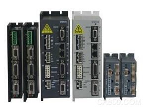
CANopen and EtherCAT are open standard protocols for network motion control internationally. They can simplify wiring, reduce costs, enhance diagnostic capabilities, and more. CANopen is mainly used in distributed control systems, and EtherCAT can be applied in both centralized and distributed control structures. Each network has its own advantages. Tyco Intelligent provides a complete stepping and servo drive control solution for these two network control structures. At the same time, related software tools are provided to simplify system debugging and easy migration from the CANopen network to the EtherCAT network.
2. Centralized and Distributed Motion Control:
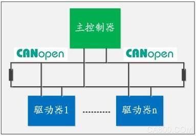
System tasks are ranked and assigned as shown in the figure below. Green indicates the controller and blue indicates the driver. In a centralized structure, all tasks except the current loop are done by the controller. The current loop should be updated at least every 100 μs. This places a very high computational burden on the controller and must use high-speed data communication links.
In a distributed control system, all servo loops are completed within the drive. In profile mode (downloading motion parameters and starting the run), the drive also performs path planning internally. The driver does not need to add additional cost, and can save the motion control card. Since the refresh rate of the position loop is much lower than that of the current loop, only a low-speed network can be used.
centralized
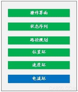
More suitable for highly coupled shafts such as robots
More efficient real-time servo loop adjustment
·Require higher bandwidth network
distributed
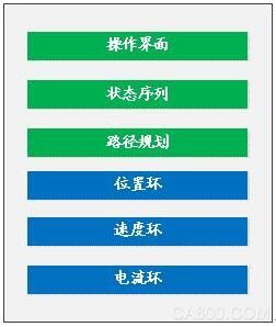
Ideal for point-to-point and most contour curves
Low-cost solution, minimize drive size
Only requires low bandwidth network
Easy to expand, no increase in controller burden
3. PVT path planning:
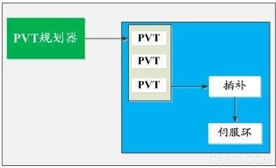
In distributed control cooperative motion systems, both EtherCAT and CANopen use PVT for path planning: the controller generates a series of points to define the position and velocity values ​​of each axis at a given time. PVT path planning is a very efficient method of defining motion trajectories.
In general, the track point is sent to the driver's buffer every 10ms. The driver implements third-order interpolation to generate the optimal curve. After interpolation, the position loop on each drive is updated synchronously at a rate of several kilohertz.
4. Network speed and efficiency:
For a network of motion control systems, efficiency, decisiveness, and synchronization are far more important than speed. Standard Ethernet has a transmission speed that is more than 100 times faster than CANopen, but is primarily designed for asynchronous transmission of large data files. The message conflict on the network is devastating and must be resent. CANopen was mainly created for low-cost transmission of real-time small data packets. For distributed control, it can fully meet its real-time requirements.
EtherCAT brings synchronization and determinism to Ethernet. EtherCAT is obviously the most effective compared to many standard Ethernets modified in real time. For a distributed control system, it satisfies the requirement of refreshing the speed of the driver current loop and can flexibly transmit PVT points. However, EtherCAT drives are more expensive and have a slightly larger footprint than comparable CANopen drives.
Second, technical overview
1. Introduction to CANopen:
CANopen is an open standard application layer built on the CAN data link layer. CAN was originally developed for automotive applications and has been proven to be a rugged, reliable, and economical communications network. Master/slave and peer-to-peer communication can occur, and message collisions are not devastating.
The slave axis synchronizes with the distributed clock marked by the locked time. Parameters and real-time data are processed by SDOs and PDOs, respectively, to achieve optimal efficiency. For a complete system solution, third-party I/O and control software can be supported.
2. Network topology and bus arbitration:
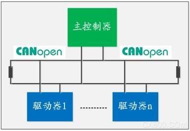
CAN is a multi-drop network using a simple twisted pair connection. The maximum speed is up to 1Mb/s and the line length is up to 40 meters. Both ends of the network must be connected with termination resistors, and the end lines should be as short as possible. A CAN network can support up to 127 nodes.
When the bus is free, any node can send data. The message frame starts sending the identifier of this message with the frame valid low start bit. The lower the identifier, the higher its priority. If two devices send data to the network at the same time, devices with a high priority identifier will force the bus level to be pulled low, while low-priority node devices will recognize this condition and will abandon the use of the bus.
3. Synchronization:
Synchronization between CANopen slave axes can be achieved in a matter of milliseconds. At startup, a designated slave sends a synchronization message to establish a network time reference, and the latest actual time of the synchronization message (defined by the slave's internal clock) is periodically broadcasted to other synchronization axes. Each sync axis will use this time stamp to constantly adjust its own clock to keep the sync locked.
4. SDOs and PDOs:
SDOs are primarily used for asynchronous transfer of slave axis configuration parameters. Some of the 8 bytes of the CAN data field define the position of the configuration parameter in the slave axis. If the packet is 4 bytes, only one CAN frame is required, although the slave must respond to this SDO. In subsequent frames, longer data packets can be sent in 7-byte blocks.
PDOs provide an efficient way to transfer real-time data packets of 8 bytes or less. All 8 bytes of data fields are available for this method because PDO has been mapped to the corresponding slave axis control function in advance. A PVT vector can be sent in a CAN frame. PDOs can also be initialized by a slave axis just as if an interrupt were sent to the master.
5. Introduction to EtherCAT:
EtherCAT is an open standard created for real-time control. Fast and decisive, EtherCAT can be within 100us with refreshing 100 slaves with 8 bytes of data. It supports all network topologies and can use copper cables or fiber optics as a medium. EtherCAT makes use of CANopen and SERCOS device configurations to make migration easier and more convenient. The EtherCAT host controller uses standard hardware and does not require an additional communications processor. Using a custom ASIC or FPGA for the slave axis, the cost can be negligible compared to a standard Ethernet node.
6. Message and Network Topology:
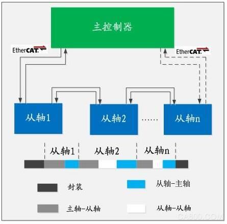
EtherCAT optimizes network bandwidth by setting a unique time slot for the slave axis in a standard Ethernet packet. Each slave axis reads the data of the spindle and inserts its own data when the message passes. This data can also be used as the primary controller for downstream nodes.
The most common EtherCAT topology is linear. Since EtherCAT is full-duplex communication, the last node is connected back to the host (constituting the loop) to provide network redundancy. EtherCAT supports up to 65,535 nodes with a length of up to 100 meters between nodes.
EtherCAT can adapt to a star topology, but this topology requires the slave axis to operate in open loop mode. In the current ASIC-implemented slave axis, open-loop mode is not yet available. However, a star topology can be used with Tyco's intelligent servo drivers designed based on more flexible FPGA technology.
7. EtherCAT synchronization:
Like CANopen, EtherCAT uses a distributed clock to synchronize network nodes. The spindle uses time stamp information from each slave axis to adjust the distributed clock. Even with hundreds of nodes, the synchronization time error may be less than 1us.
8. CANopen over EtherCAT (CoE):
CANopen over EtherCAT implements standard SDO and PDO communication mechanisms. Even network management is very similar: Application code can be reused and easily ported to EtherCAT. CANopen device properties can also be extended to high bandwidth EtherCAT.
Control software
Tyco's intelligent distributed control software makes the system's commissioning quick and easy. Controls CANopen or EtherCAT without low-level code development. All network management only needs to notice some simple commands that have been linked to the application.
Tyco Smart supports two development environments, MLC: (C++ Motion Library) linked to a C++ application; MLO: (COM Target Library) can be used with Visual Basic, .NET, LabVIEW, or any COM-compatible software. The application code and the control object for the servo or stepper driver are interfaced in the MLC/MLO function library. These objects can be linked to CANopen or EtherCAT's communication objects. Whether implementing CANopen or EtherCAT, the basic application code remains unchanged and can be easily migrated from the CANopen network to the EtherCAT network. EtherCAT and CANopen can also be combined on the same PC.
Network management
· Configuration and startup
·Synchronize
· Message generation
·Error Management
sport control
·route plan
·PVT generation
·Execution curve
·PVT buffer management
Universal
· Set/get parameters
·Download settings file
Driver error handling
·I/O interface
2. Network Solutions:
For CANopen Networks, Tyco Smart offers an on-board microcontroller and dual channel PCI card. The card with CANView supports network diagnostics, message display and bus load analysis.
Tyco Smart Drives have comprehensive local I/O features to reduce the need for third-party devices. The EtherCAT PCB Mount Driver Module also includes a high-speed SPI interface to facilitate a large number of I/O expansions.
Tyco intelligent I/O processor modules with 72 digital I/Os and 12 analog inputs allow OEMs to design optimal system interfaces and seamlessly integrate them into control systems.
3. EtherCAT master controller:
In a distributed control structure with a servo closed loop in the drive, MLC and MLO make a customized host very close to the OEM. There are also many third-party EtherCAT host controllers available. These products are mainly used to complete software tasks and require a PC with a real-time multitasking operating system.
Suppliers of EtherCAT host controllers include:
·Beckoff (TwinCAT)
·Acontis Technologies
·Soft Servo
·ACS Motion Control
·3S (CoDeSys)
·Koenig Process Automation
4. Migrating from CANopen to EtherCAT:
CANopen is a proven and reliable low-cost solution for distributed control that meets the needs of most applications. For centralized multi-axis highly-coupled control that requires real-time adjustment of the servo loop, selecting EtherCAT is more appropriate. Network topology, number of nodes, and cables are also factors to consider when selecting EtherCAT. The advantages and disadvantages of porting from CANopen to EtherCAT are summarized as follows:
Advantages Disadvantages:
· Centralized control for high coupling between shafts · Increased drive costs
· Flexible line topology with redundant · Increased drive dimensions
Longer communication distance (100m) • The driver must consider the influence of the signal transmission line when PCB layout
· Theoretically speaking, there are no restrictions on the number of network nodes
·High speed communication from axis to slave axis
Standard Ethernet interface, no need for CAN card
Capacitor Leakage Test Power Supplies
The ADP series capacitor leakage test power supply is specially designed and customized for capacitor manufacturers` product quality control process or users of capacitors for capacitor ripple current durability life test.
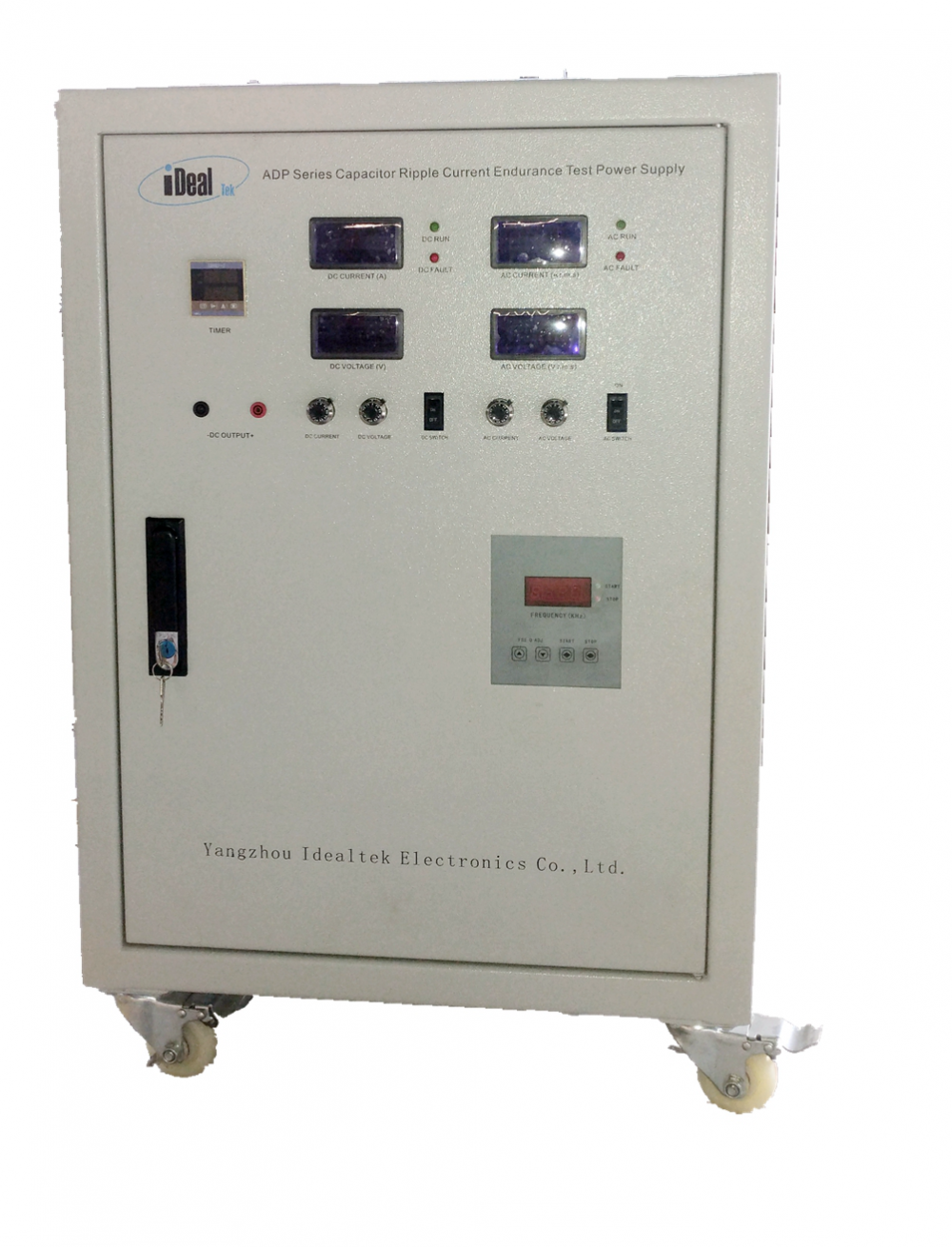
Capacitor leakage current test power supply is aimed at the diversity of output voltage and frequency required for different capacitance tests with the DC output voltage up to 3000Vdc, the AC voltage output up to 200Vac, the AC current up to 500A, and the output frequency can be selected according to customer requirements from 50Hz to 100KHz.
Equipped with special high-frequency and high-temperature fixtures and connecting wires for capacitor leakage current testing, the capacitor leakage current test power supply can imitate the actual working conditions of capacitors to determine the service life of a group of capacitors under test, providing the accurate parameters of capacitors required by the manufacturer for the capacitors R&D and quality inspection test, the power supply is now aiding the test of high-frequency and high-current passive devices such as high-frequency capacitors, film capacitors, electrolytic capacitors, ballast capacitors, and ballast inductors.
Capacitor Leakage Current Power Supplies, Leakage Current Ripple Power Supplies, AC and DC Power Supplies, Capacitor Test Power Supplies, Ripple Current Test Power Supplies
Yangzhou IdealTek Electronics Co., Ltd. , https://www.idealtekpower.com