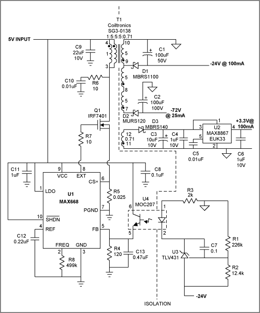
Some subscriber line interface cards (SLICs) require power-supply voltages isolated from the local supply. The Figure 1 circuit generates three such isolated voltages from a 5V input: + 3.3V at 100mA, -24V at 100mA, and -72V at 25mA. It features a boost controller (U1) operaTIng in a transformer flyback topology, and an optocoupler for isolaTIng the feedback signal. To provide this feedback (from the -24V output to the boost controller) the optocoupler (U4) is driven by a shunt voltage regulator (U3) acTIng as an error amplifier.

Figure 1. This SLIC power supply isolates the three outputs (+ 3.3V, -24V, and -72V) with a transformer, and isolates the feedback signal with an optocoupler.
The wide range of output voltages requires a custom transformer. Its core is a standard-geometry Coiltronics SG3-0138 with AL = 138nH / T². The primary inductance is 6.8µH, and the peak primary current is 4A. The primary-to-secondary turns raTIo is 1: 5, so for best efficiency the converter operates with a duty cycle near 50%. The unregulated -72V output is derived from the regulated -24V output via three identical secondary windings connected in series. Also available is a tap for a -48V output, and a low-voltage winding that drives a linear voltage regulator (U2) to provide the + 3.3V output. The transformer's winding specs are:
At maximum specified load with an input of 5.0V at 1.138A, the circuit yields 80% efficiency while delivering + 3.28V at 103.9mA, -24.0V at 100mA, and -73.2V at 25.2mA.
Notes: T1 is wound on a standard geometry core with 138nH / T².
Primary inductance is 6.7µH.
Primary is 7 turns of # 28 bifilar.
Tapped secondary is three layers of 35 turns each of # 32 per tap.
Low voltage secondary is 5 turns of # 32.
A similar version of this article appeared in the September 24, 2001 issue of EE Times magazine.

Figure 1. This SLIC power supply isolates the three outputs (+ 3.3V, -24V, and -72V) with a transformer, and isolates the feedback signal with an optocoupler.
The wide range of output voltages requires a custom transformer. Its core is a standard-geometry Coiltronics SG3-0138 with AL = 138nH / T². The primary inductance is 6.8µH, and the peak primary current is 4A. The primary-to-secondary turns raTIo is 1: 5, so for best efficiency the converter operates with a duty cycle near 50%. The unregulated -72V output is derived from the regulated -24V output via three identical secondary windings connected in series. Also available is a tap for a -48V output, and a low-voltage winding that drives a linear voltage regulator (U2) to provide the + 3.3V output. The transformer's winding specs are:
| Primary: | 7T | 28AWG bifilar |
| Secondary: | 35T | 32AWG |
| 35T | 32AWG | |
| 35T | 32AWG | |
| 5T | 32AWG |
At maximum specified load with an input of 5.0V at 1.138A, the circuit yields 80% efficiency while delivering + 3.28V at 103.9mA, -24.0V at 100mA, and -73.2V at 25.2mA.
| VIN (V) | Iin (A) | Vo (V) | Io (mA) | Vo (V) | Io (mA) | Vo (V) | Io (mA) | Eff. (%) |
| 4.50 | 1.27 | 24.01 | 100.2 | 73.2 | 25.2 | 3.28 | 103.9 | 80.3 |
| 5.01 | 1.138 | 24.01 | 100.2 | 73.2 | 25.2 | 3.28 | 103.9 | 80.5 |
| 5.50 | 1.038 | 24.01 | 100.2 | 73.2 | 25.2 | 3.28 | 103.9 | 80.4 |
Primary inductance is 6.7µH.
Primary is 7 turns of # 28 bifilar.
Tapped secondary is three layers of 35 turns each of # 32 per tap.
Low voltage secondary is 5 turns of # 32.
A similar version of this article appeared in the September 24, 2001 issue of EE Times magazine.
UGR LED Downlight,LED Recessed Downlight,UGR Adjust LED Downlight,UGR LED Commercial Downlight
SHENZHEN KEHEI LIGHTING TECHNOLOGY CO.LTD , https://www.keheiled.com