With the LDC1000 inductor/digital converter as the core, a car that can automatically follow the shape of the wire is designed and manufactured. The main functional modules of the system include: main control module, metal signal detection module, speed detection module, motor drive module and power module. The system main control chip STC89C52 judges whether the trolley deviates from the orbit according to the detected metal distance signal, thereby making a direction adjustment, so that the trolley can automatically track in a certain direction on the specified plane runway.
Widely used in tracking is very much in industrial automation and systems, and there are many ways to track them, each with its own shortcomings. Mechanical chain track has wear and occupy place; photoelectric slow reflection detection type requires black track and is affected by Ambient Light; camera pattern recognition requires a good recognition algorithm and is affected by ambient light.
Based on this, this paper uses LDC1000 to detect and judge the wire and realize the automatic tracking application.
Introduction to LDC1000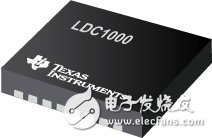
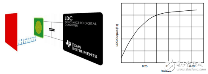
The LDC1000 is a new Inductor-to-Digital Converter (LDC) from TI, USA. It has the advantages of low power consumption, small package and low cost. Its SPI interface makes it easy to connect to the MCU. The LDC1000 requires only one external PCB coil or a self-made coil for non-contact inductive sensing. Inductance detection of the LDC1000 does not refer to testing the inductance of the coil like the Q meter, but can test the spatial positional relationship of the external metal object and the test coil connected to the LDC1000.
It can be easily realized by using the LDC1000 with externally designed metal objects, horizontal or vertical distance detection; angle detection; displacement monitoring; motion detection; vibration detection; metal component detection; can be widely used in automobiles, consumer electronics, computers, Industrial, communications and medical fields.
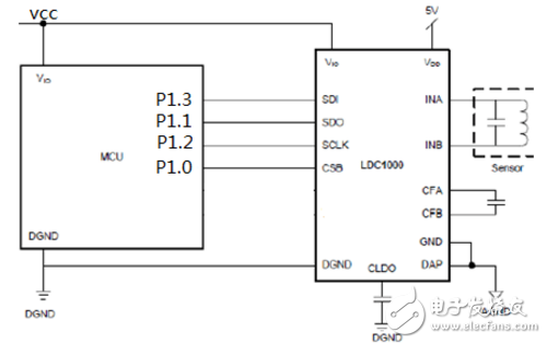
Mcu and LDC1000 interface diagram
When using the oc port of the stc89c52 to simulate the spi interface, and when communicating with the slave (LDC1000), the following steps should be followed:
Chip select signal is set to zero;
Stc89c52 writes the access register address to the LDC1000 through the analog SPI line, where the highest bit 0 indicates writing, 1 indicates readout, and the remaining 7 bits are the address of the register;
Occupies eight clock cycles during which the SDO line is in a high-impedance state;
If the command is in the read/write state, the highest bit of the transmitted data is 1, and the SDO sends the 8-bit byte from the other address registers online;
If the command is in the read/write state, the SDI line receives the 8-bit byte data from stc89c52 and writes it to the corresponding register;
The chip select signal is set high to release control of the slave.
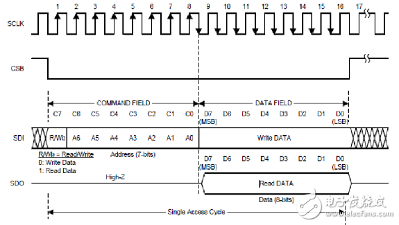
LDC1000 SPI read and write timing diagram
Stc89c52 Driver Design
The following driver is designed according to the SPI interface timing of the LDC1000:
// read 1B data
Unsigned char Ldc_SPIread(void);
/ / Write 1B data
Void Ldc_SPIwrite(unsigned char ch);
/ / write register
Void LDC1000_WriteReg(unsigned char addr, unsigned char dat);
//Read register
Unsigned char LDC1000_ReadReg(unsigned char addr);
/ / Chip initialization
Void LDC1000_Init(void);
/ / Read distance parameters
Unsigned int ReadValue(void);
Control logicThe front of the car is equipped with an inductive antenna. When the car is driving along the wire, due to special reasons (such as uneven road surface, asymmetrical wheel of the car, etc.) , the car body deviates from the track and there are three cases of A, B and C. (As shown below).

A, B, C Under the antenna of the three cases, the value obtained by the function ReadValue() is Fa, Fb, Fc. The relationship between the three is Fa "Fb, Fc "Fb. For this reason, when the value is detected as Fb When the car goes straight, otherwise the car turns. Turn left and turn right to adjust according to the width of the turn. The program flow is as follows:
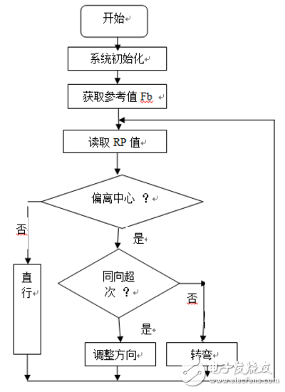
According to the above principle, the system track, the experimental car, and the wire data monitored by the serial port detection system are produced. The diameter of the wire is more than 0.9mm, and the tracking car includes the control board, display, photoelectric speed measurement, motor, Bluetooth transceiver module and so on. The sampled data is monitored based on whether the body is off track.
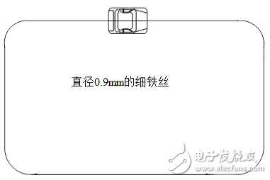
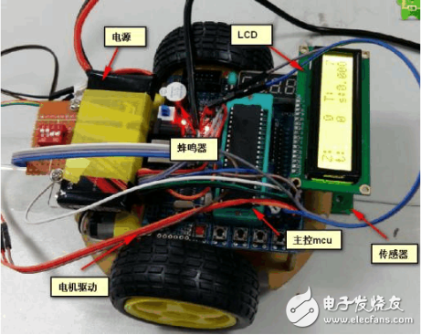
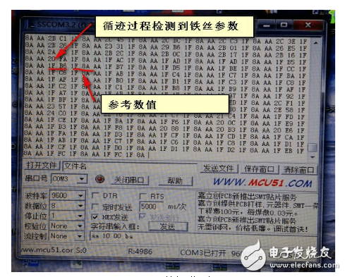
Non-contact inductive coil detection can be realized by using PCB coil or self-made coil, and metal detection can be conveniently realized by analyzing the influence of the metal object to be tested on the magnetic field of the induction coil. After the actual measurement, the metal of 3cm distance can be effectively detected by setting the module register value reasonably. External Lighting conditions do not have much impact on the system, and must also be able to quickly detect metal within a certain distance and identify the type of metal.
Attached: LDC1000 driver
#include "reg52.h"
// LDC COMMANDS
#define LDC1000_CMD_REVID 0x00
#define LDC1000_CMD_RPMAX 0x01
#define LDC1000_CMD_RPMIN 0x02
#define LDC1000_CMD_SENSORFREQ 0x03
#define LDC1000_CMD_LDCCONFIG 0x04
#define LDC1000_CMD_CLKCONFIG 0x05
#define LDC1000_CMD_THRESHILSB 0x06
#define LDC1000_CMD_THRESHIMSB 0x07
#define LDC1000_CMD_THRESLOLSB 0x08
#define LDC1000_CMD_THRESLOMSB 0x09
#define LDC1000_CMD_INTCONFIG 0x0A
#define LDC1000_CMD_PWRCONFIG 0x0B
#define LDC1000_CMD_STATUS 0x20
#define LDC1000_CMD_PROXLSB 0x21
#define LDC1000_CMD_PROXMSB 0x22
#define LDC1000_CMD_FREQCTRLSB 0x23
#define LDC1000_CMD_FREQCTRMID 0x24
#define LDC1000_CMD_FREQCTRMSB 0x25
Sbit PIN_LDC_CS=P1^0;
Sbit PIN_LDC_SO=P1^1;
Sbit PIN_LDC_SCK=P1^2;
Sbit PIN_LDC_SI=P1^3;
#define SET_PIN_LDC_SI(bValue) PIN_LDC_SI=bValue
#define GET_PIN_LDC_SO() PIN_LDC_SO
#define SET_PIN_LDC_SCK(bValue) PIN_LDC_SCK=bValue
#define SET_PIN_LDC_CS(bValue) PIN_LDC_CS=bValue
/*------------------------------------------------ --------------- Function: Read 1B data input: No output: 1B data----------------------- -----------------------------------------*/
Unsigned char Ldc_SPIread(void)
{
Unsigned char i = 0;
Ch = 0;
For(i = 0; i " 8; i ++)
{
SET_PIN_LDC_SCK(0);
Ch "" 1;
SET_PIN_LDC_SCK(1);
If(GET_PIN_LDC_SO())ch = ch | 0x01;
}
SET_PIN_LDC_SCK(0);
Return (ch);
}
/*------------------------------------------------ --------------- Function: Write 1B data input: ch--1B data output: None -------------------- --------------------------------------------*/
Void Ldc_SPIwrite(unsigned char ch)
{
Unsigned char i = 0;
For(i = 0;i " 8;i ++)
{
SET_PIN_LDC_SCK(0);
If(ch & 0x80) SET_PIN_LDC_SI(1);
Else SET_PIN_LDC_SI(0);
SET_PIN_LDC_SCK(1) ch "= 1;
}
SET_PIN_LDC_SCK(0)
}
/ / write register
Void LDC1000_WriteReg(unsigned char addr, unsigned char dat)
{
Addr = addr & 0x7F;
SET_PIN_LDC_CS (0);
Ldc_SPIwrite( addr);
Ldc_SPIwrite( dat);
SET_PIN_LDC_CS (1);
}
//Read register
Unsigned char LDC1000_ReadReg(unsigned char addr)
{
Unsigned char temp;
Addr = addr | 0x80;
SET_PIN_LDC_CS (0);
Ldc_SPIwrite( addr);
Temp = (UINT8)Ldc_SPIread();
SET_PIN_LDC_CS (1);
Return temp;
}
/ / Chip initialization
Void LDC1000_Init(void)
{
LDC1000_WriteReg(LDC1000_CMD_RPMAX, 0x13);
LDC1000_WriteReg(LDC1000_CMD_RPMIN, 0x3A);
LDC1000_WriteReg(LDC1000_CMD_SENSORFREQ, 0x94);
LDC1000_WriteReg(LDC1000_CMD_LDCCONFIG, 0x17);
LDC1000_WriteReg(LDC1000_CMD_CLKCONFIG, 0x02);
LDC1000_WriteReg(LDC1000_CMD_INTCONFIG, 0x02);
LDC1000_WriteReg(LDC1000_CMD_THRESHILSB, 0x50);
LDC1000_WriteReg(LDC1000_CMD_THRESHIMSB, 0x14);
LDC1000_WriteReg(LDC1000_CMD_THRESLOLSB, 0xC0);
LDC1000_WriteReg(LDC1000_CMD_THRESLOMSB, 0x12);
LDC1000_WriteReg(LDC1000_CMD_PWRCONFIG, 0x01);
}
/ / Read distance parameters
Unsigned int ReadValue(void)
{
Unsigned int iTemp;
iTemp= LDC1000_ReadReg(LDC1000_CMD_PROXMSB);
iTemp "=8;
iTemp+= LDC1000_ReadReg(LDC1000_CMD_PROXLSB);
Return iTemp;
}
High Speed Blender,Ipl Laser Hair Removal,Diy Laser Hair Removal,Best Ipl Hair Removal,Epilator Ipl
SHENZHEN CHONDEKUAI TECHNOLOGY CO.LTD , https://www.szsiheyi.com