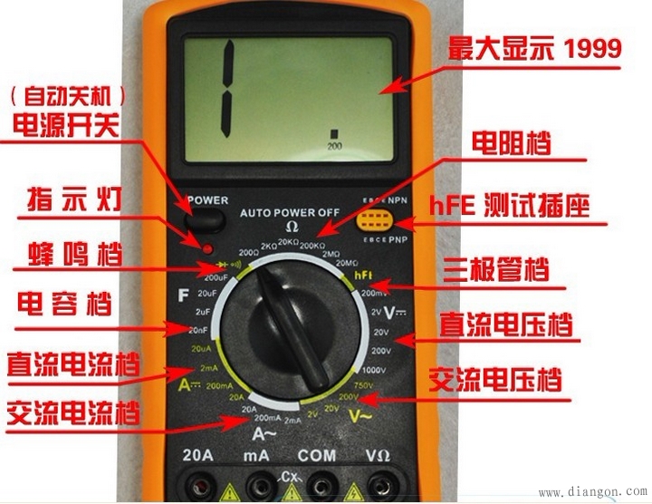
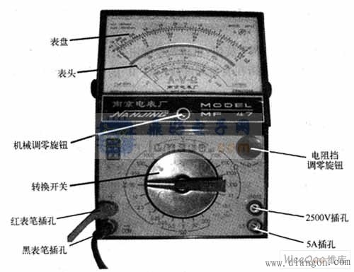
1. The pointer table reading accuracy is poor, but the process of pointer swing is relatively intuitive, and the amplitude of the swing speed can sometimes objectively reflect the measured size (such as measuring the slight difference of the TV data bus (SDL) when transmitting data. Jitter); the digital meter reads intuitively, but the process of digital changes looks messy and not easy to watch.
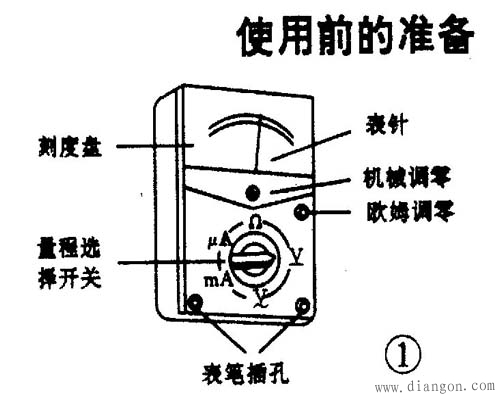
2. There are generally two batteries in the pointer table, one low voltage 1.5V, one high voltage 9V or 15V, and the black test pen is the positive end relative to the red test pen. Digital watches are often used with a 6V or 9V battery. In the resistance file, the output current of the meter in the pointer table is much larger than that of the digital meter. The R×1Ω file can make the speaker emit a loud “beep†sound, and even the LED can be lit by the R×10kΩ file.
3. In the voltage file, the internal resistance of the pointer table is relatively small compared with the digital meter, and the measurement accuracy is relatively poor. Some high-voltage micro-currents can't even be measured because their internal resistance will affect the circuit under test (for example, when measuring the accelerating voltage of a TV tube, the measured value will be much lower than the actual value). The internal resistance of the digital meter voltage file is very large, at least in the mega-ohm range, and has little effect on the circuit under test. However, the extremely high output impedance makes it susceptible to induced voltage, and the data measured in some cases where electromagnetic interference is relatively strong may be virtual.
4. In short, the pointer table is used in the analog circuit measurement of relatively high current and high voltage, such as TV set and audio power amplifier. Digital meters, such as BP machines, mobile phones, etc., are used in the measurement of digital circuits with low voltage and low current. Not absolute, the pointer table and the digital table can be selected according to the situation.
Second, the measurement skills (if not stated, it refers to the pointer table):
1. Test the horn, earphone, and dynamic microphone: use R×1Ω file, one of the pens is connected to one end, and the other pen touches the other end. When normal, it will emit a “beep†sound. If it doesn't ring, the coil is broken. If the sound is small and sharp, there is a problem with the rubbing circle.
2, measuring capacitance: use the resistance file, according to the capacity of the capacitor to select the appropriate range, and pay attention to the measurement of the electrolytic capacitor black pen to the capacitor positive. 1. Estimate the size of the microwave-level capacitor capacity: It can be judged according to the maximum amplitude of the pointer swing by experience or by referring to the standard capacitance of the same capacity. The capacitors to be referenced do not have to have the same withstand voltage values, as long as the capacities are the same. For example, it is estimated that a 100μF/250V capacitor can be referenced by a 100μF/25V capacitor, and as long as their pointer swings to the same maximum amplitude, the capacity can be determined. 2, estimate the size of the skin-level capacitor capacity: use R × 10kΩ file, but can only measure more than 1000pF capacitor. For a 1000pF or slightly larger capacitor, as long as the hands are slightly swung, the capacity is considered sufficient. 3. Measure whether the capacitor leaks: For a capacitor of more than one thousand microfarads, it can be quickly charged with R×10Ω file, and the capacitance capacity is initially estimated, then changed to R×1kΩ file and continue to measure for a while, then the pointer is not It should be returned, but should be parked at or very close to the place, otherwise there will be leakage. For some timing or oscillating capacitors below tens of microfarads (such as the oscillating capacitor of color TV switching power supply), the leakage characteristics are very high, as long as there is a slight leakage, it can not be used. At this time, after the R×1kΩ gear is charged, Then continue to use R × 10kΩ file to continue measurement, the same needle should stop at the ∞ and should not return. ()
3. In the road test diode, triode, and voltage regulator, it is good or bad: because in the actual circuit, the bias resistance of the triode or the peripheral resistance of the diode and the voltage regulator are generally large, mostly in the hundreds of thousands of ohms or more. , we can use the multimeter's R × 10 Ω or R × 1 Ω file to measure the quality of the PN junction in the road. When measuring the road, the PN junction measured by R×10Ω should have obvious positive and negative characteristics (if the difference between the forward and reverse resistance is not obvious, it can be measured by R×1Ω), and the general forward resistance is in R. When the ×10Ω is measured, the hands should be indicated at about 200Ω. When the R×1Ω is measured, the hands should be indicated at 30Ω (may vary slightly depending on the phenotype). If the measured value of the forward resistance is too large or the reverse resistance is too small, it indicates that there is a problem with this PN junction, and this tube is also problematic. This method is particularly effective for maintenance, can find the bad tube very quickly, and can even measure the tube that has not completely broken but the characteristics are deteriorated. For example, when you measure a PN junction with a small resistance value, the forward resistance is too large. If you solder it down and use the commonly used R×1kΩ file, it may still be normal. In fact, the characteristics of this tube have deteriorated. Not working or unstable.
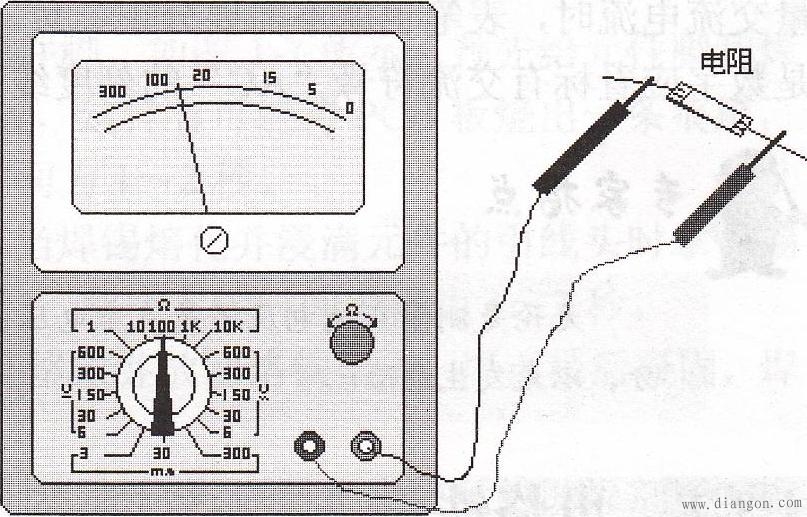
4. Measuring resistance: It is important to select the range. When the pointer indicates 1/3~2/3 full scale, the measurement accuracy is the highest and the reading is the most accurate. It should be noted that when measuring the large resistance value of the ohms level with the R×10k resistance file, the fingers should not be pinched at both ends of the resistor, so that the human body resistance will make the measurement result smaller. For the common imported high-power plastic tube, the c-pole is basically in the middle (I have not seen b in the middle). The b poles of the medium and small power tubes may be in the middle. For example, the commonly used 9014 triode and other series of triodes, 2SC1815, 2N5401, 2N5551 and other triodes, the b pole is in the middle. Of course, they also have c in the middle. Therefore, when repairing and replacing the triode, especially these low-power triodes, if they are not used, they should be installed directly as they are, and must be measured first.
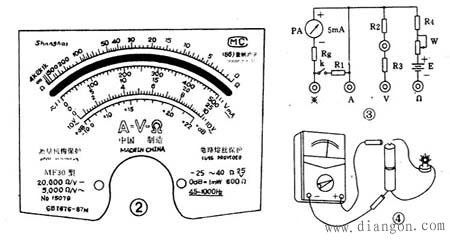
Third, the detection method of the integrated circuit using only the multimeter as a detection tool Although the integrated circuit is replaced, the disassembly is troublesome after all. Therefore, before demolition, it should be determined exactly whether the integrated circuit is indeed damaged or damaged, and avoid blind disassembly. This article describes the methods and considerations for detecting integrated circuits in the out-of-road and on-the-road using only a multimeter as a detection tool. The four methods of detecting in-circuit (DC resistance, voltage, AC voltage, and total current measurement) described in this paper are practical and commonly used in amateur maintenance. Here, I also hope that you can provide other practical (integrated circuits and components) discriminating and testing experience.
1. In-circuit detection This method is performed when the IC is not soldered into the circuit. In general, a multimeter can be used to measure the positive and negative resistance values ​​of each pin corresponding to the ground pin, and compared with the intact IC. .
Second, in the road detection This is a multi-meter detection IC pin on the way (IC in the circuit) DC resistance, ground AC and DC voltage and total operating current detection method. This method overcomes the limitation that the replacement test method needs to replace the IC and the trouble of disassembling the IC, and is the most common and practical method for detecting the IC.
1. In-circuit DC resistance detection method This is a method for detecting and determining faults by measuring the forward and reverse DC resistance values ​​of IC pins and peripheral components directly on the circuit board with a multimeter ohms block and comparing with normal data. . Pay attention to the following three points when measuring:
(1) Disconnect the power supply before measuring to avoid damage to the meter and components during testing.
(2) The internal voltage of the multimeter's electrical blocking shall not exceed 6V, and the range is preferably blocked by R×100 or R×1k.
(3) When measuring the IC pin parameters, pay attention to the measurement conditions, such as the model to be tested, the position of the sliding arm of the potentiometer associated with the IC, etc., and also consider the quality of the peripheral circuit components.
2. DC working voltage measurement method is a kind of measurement of the DC supply voltage and the operating voltage of the peripheral components by the multimeter DC voltage block under the condition of power-on; detecting the DC voltage value of each pin of the IC to the ground, and comparing with the normal value, In turn, the fault range is compressed to find the damaged component. Pay attention to the following eight points when measuring:
(1) The multimeter should have a large internal resistance, at least 10 times greater than the resistance of the circuit under test, so as not to cause a large measurement error.
(2) Usually, each potentiometer is rotated to the middle position. If it is a TV set, the signal source should use a standard color bar signal generator.
(3) The test leads or probes should be anti-slip. It is easy to damage the IC due to any short circuit. The following method can be used to prevent the pen from sliding: take a valve core of the bicycle and set it on the tip of the watch, and grow the tip of the watch to about 0.5mm, which can make the tip of the watch be in good contact with the tested point, and can effectively prevent slippage. Even if it hits an adjacent point, it will not short-circuit.
(4) When the measured voltage of a pin does not match the normal value, it should be analyzed according to whether the voltage of the pin has an important influence on the normal operation of the IC and the corresponding change of the voltage of other pins, in order to judge whether the IC is good or bad.
(5) The IC pin voltage is affected by peripheral components. When the peripheral components are leaking, short-circuited, open-circuited or variable, or the peripheral circuit is connected to a potentiometer with variable resistance, the position of the potentiometer sliding arm is different, which will change the pin voltage.
(6) If the voltage of each pin of the IC is normal, the IC is generally considered to be normal; if the voltage of the pin of the IC is abnormal, it should start from the maximum deviation from the normal value to check whether the external components are faulty. If there is no fault, the IC is likely to be damaged. .
(7) For dynamic receiving devices, such as televisions, the voltage at each pin of the IC is different when there is no signal. If it is found that the voltage of the pin does not change, the change is large, and the change of the signal size and the position of the adjustable component does not change, and the IC damage can be determined.
(8) For devices with multiple working modes, such as video recorders, the voltage of each pin of the IC is different under different working modes.
3. AC working voltage measurement method In order to grasp the change of the IC AC signal, the AC working voltage of the IC can be approximated by a multimeter with a dB jack. When testing, the multimeter is placed in the AC voltage block, and the positive pen is inserted into the dB jack. For a multimeter without a dB jack, a 0.1 to 0.5 μF DC blocking capacitor is connected in series with the positive pen. This method is applicable to ICs with relatively low operating frequencies, such as video amplification stages and field scanning circuits of televisions. Since the natural frequencies of these circuits are different and the waveforms are different, the measured data is an approximation and can only be used for reference.
4. Total Current Measurement This method is a method for judging the quality of an IC by detecting the total current of the IC power supply line. Since most of the IC is directly coupled, when the IC is damaged (such as a PN junction breakdown or open circuit), it will cause the latter stage to be saturated and cut off, causing the total current to change. Therefore, the method of measuring the total current can judge the quality of the IC. It is also possible to measure the voltage drop of the resistor in the power path and calculate the total current value using Ohm's law. (http://)
The above detection methods have their own advantages and disadvantages. In practical applications, it is best to combine various methods and use them flexibly.
Fourth, how to use the multimeter to detect thyristor thyristor unidirectional thyristor and two-way thyristor, are three electrodes. The unidirectional thyristor has a cathode (K), an anode (A), and a gate (G). The two-way thyristor is equivalent to the reverse parallel connection of two single thyristors. That is, one of the unidirectional silicon anodes is connected to the other cathode, and the leading end is called the T2 pole. One of the unidirectional silicon cathodes is connected to the other anode, and the leading end is called the T2 pole, and the remaining is controlled. Extreme (G).
1. Discrimination of single and two-way thyristor: firstly measure two poles, if the positive and negative probes are not moving (R×1 block), it may be A, K or G, A pole (for unidirectional thyristor) It may also be T2, T1 or T2, G pole (for two-way thyristor). If one of the measurement indications is tens to hundreds of ohms, it must be a unidirectional thyristor. And the red pen is connected to the K pole, the black pen is connected to the G pole, and the rest is the A pole. If the positive and negative measurement instructions are tens to hundreds of ohms, it must be a two-way thyristor. Then turn the knob to R×1 or R×10, and the resistance must be slightly larger. The slightly larger red pen is connected to the G pole, the black pen is connected to the T1 pole, and the rest is the T2 pole. .
2, the difference in performance: the knob is set to R × 1 block, for 1 ~ 6A one-way thyristor, red pen connected to K pole, black pen simultaneously connected to G, A pole, while keeping the black pen does not leave the A pole state When the G pole is disconnected, the pointer should indicate tens of ohms to one hundred ohms. At this time, the thyristor has been triggered and the trigger voltage is low (or the trigger current is small). Then, the A pole is turned off and then turned on again, and the pointer should be returned to the ∞ position, indicating that the thyristor is good.
For 1~6A two-way thyristor, the red pen is connected to the T1 pole, and the black pen is connected to the G and T2 poles at the same time. When the black pen is not separated from the T2 pole, the G pole is disconnected, and the pointer should be indicated as tens to more than one hundred. Europe (depending on the size of the thyristor and the manufacturer). Then, the two strokes are reversed, and the above steps are repeated once. The pointer indication is slightly larger than the previous one by a few ten to several tens of ohms, indicating that the thyristor is good and the trigger voltage (or current) is small.
If the G pole is turned off while the A or T2 pole is turned on, the pointer immediately returns to the ∞ position, indicating that the thyristor trigger current is too large or damaged. It can be further measured according to the method of Fig. 2. For the unidirectional thyristor, the switch K should be closed, the lamp should be bright, and the K lamp will not be extinguished, otherwise the thyristor is damaged.
For the two-way thyristor, close the switch K, the lamp should be lit, disconnect K, the lamp should not be extinguished. Then reverse the battery and repeat the above steps, all of which should be the same result, which is good. Otherwise the device is damaged.
5. Precautions for the use of the multimeter (1) Before using the multimeter, perform “mechanical zeroingâ€, that is, when there is no measured power, the multimeter pointer points to the zero voltage or zero current position.
(2) In the process of using the multimeter, the metal part of the test pen cannot be touched by hand, so that the measurement can be ensured on the one hand, and the personal safety can be ensured on the other hand.
(3) When measuring a certain amount of electricity, it is not possible to shift gears while measuring, especially when measuring high voltage or large current. Otherwise, the multimeter will be destroyed. If you need to change gears, you should first disconnect the test leads and then change the gears before measuring.
(4) When the multimeter is used, it must be placed horizontally to avoid errors. At the same time, we must also pay attention to avoiding the influence of external magnetic field on the multimeter.
(5) When the multimeter is used, the switch should be placed at the maximum of the AC voltage. If it is not used for a long time, the battery inside the multimeter should be taken out to prevent the battery from corroding other devices in the watch.
Sixth, the use of ohm gear First, choose the appropriate magnification. When measuring resistance on an ohmmeter, select the appropriate magnification so that the pointer is near the median. It is best not to use the left third of the scale, which is very dense.
Second, you must zero before using.
Third, can not be powered measurements.
4. The measured resistance cannot have a parallel branch.
5. When measuring the equivalent resistance of polar components such as transistors and electrolytic capacitors, you must pay attention to the polarity of the two pens.
6. When measuring the equivalent resistance of the nonlinear component with the ohmmeter of different multipliers of the multimeter, the measured resistance values ​​are different. This is caused by the difference in the median resistance and the full-scale current of each gear. In the mechanical watch, the smaller the general magnification, the smaller the measured resistance.
When the multimeter is used to measure DC, mechanical zeroing is performed.
Second, choose the appropriate range gear.
Third, when the current meter is used to measure the current, the meter should be connected in series to the sub-test circuit, because only the serial connection is such that the current flowing through the ammeter is the same as the current of the measured branch. When measuring, the measured branch should be disconnected, and the multimeter red and black test leads should be connected between the two points where the quilt is disconnected. In particular, it should be noted that the current transcription can be connected to the sub-test circuit, which is very dangerous, and it is easy to burn the meter.
Fourth, pay attention to the polarity of the measured power.
Fifth, use the scale and read correctly.
6. When selecting a 2.5A block with DC current, the multimeter red test pen should be inserted in the 2.5A measurement jack, and the range switch can be placed on any range of the DC current block.
7. If the DC current measured by the submeter is greater than 2.5A, the 2.5A gear can be expanded to 5A gear. The method is very simple, the user can connect a 0.24 ohm resistor between the "2.5A" jack and the black test lead jack, so that the gear becomes a 5A current block. The 0.24A resistor connected should be selected with a wirewound resistor of 2W or more. If the power is too small, it will burn out.
î€7. Use the multimeter to judge the positive and negative poles of the speaker. First, turn the pointer multimeter to DC 0~5mA, then connect the two test leads to the two soldering lugs of the speaker to be tested. Lightly press the speaker cone of the speaker to observe the swing direction of the multimeter pointer. If the pointer is deflected in the forward direction, the red pen is connected to the negative speaker and the black pen is connected to the positive speaker. On the contrary, the red pen is connected to the positive pole, and the black pen is connected to the negative pole.
Judging the quality of piezoelectric ceramics with a multimeter is a synthetic piezoelectric material. When subjected to external pressure, charges are generated on both sides, and the amount of charge is proportional to the pressure. This phenomenon is called the piezoelectric effect. Piezoelectric ceramics have a piezoelectric effect, that is, deformation occurs under the action of an external electric field, so a piezoelectric ceramic sheet can be used as a sounding element.
By using the piezoelectric effect of the piezoelectric ceramic sheet, the multimeter can be used to judge whether it is good or bad.
Take the two poles of the piezoelectric ceramic piece out of the two wires, then place the ceramic piece on the table flat, connect the two leads to the two test leads of the multimeter, turn the multimeter to the minimum current block, and then gently press the ceramic piece with the pencil eraser. If the pointer of the multimeter is obviously oscillated, the ceramic piece is intact, otherwise the description is damaged.
8. How to use the multimeter 1. The voltage below 36V is the safe voltage. When measuring higher than 36V DC and 25V AC, check whether the test leads are in reliable contact, whether they are connected correctly, whether they are well insulated, etc., so as to avoid electric shock.
Second, when changing functions and ranges, the test leads should leave the test point, select the correct function and range during the test, beware of misuse.
3. For DC voltage measurement, first turn the range switch to the corresponding DCV range, then connect the test lead to the circuit under test. The voltage and polarity of the point connected by the red test lead are displayed on the screen.
4. AC voltage measurement, first turn the range switch to the corresponding ACV range, and then connect the test leads across the circuit under test.
5. DC current measurement, first turn the range switch to the corresponding DCA gear position, and then string the instrument into the circuit under test.
6. AC current measurement, first turn the range switch to the corresponding ACA gear position, and then string the instrument into the circuit under test.
7. Resistance measurement, turn the range switch to the corresponding resistance range, and connect the two test leads across the measured resistance.
8. Capacitance measurement, turn the range switch to the corresponding capacitance range, connect the test leads across the measured capacitance and both ends for measurement, and pay attention to the polarity if necessary.
Nine, pole tube and continuity test, the range switch is set. Connect the red meter to the anode of the diode and the black meter to the cathode of the diode. If the line is turned on and off, connect the test leads to both ends of the line to be tested. If the buzzer sounds, the circuit is open, otherwise the circuit is disconnected.
10. Tube magnification measurement, set the range switch to hFE file, determine that the measured transistor is NPN type or PNP type, insert the emitter, base and collector into the corresponding holes.
Nine, how to use the multimeter multimeter is an essential test tool in electronic production. It has a variety of functions such as measuring current, voltage and resistance.
This section describes the structure of the multimeter and how to use the multimeter. Students should try to learn to use a multimeter.
First, observe and understand the structure of the multimeter.
There are many types of multimeters and different shapes, but the basic structure and usage are the same. The structure and shape of the commonly used multimeter are shown in the drawing on the coloring page.
The king of the universal surface board should have a meter and a selector switch. There is also an ohmic zero adjustment knob and a test lead jack. The following describes the role of each part:
(1) The header of the meter multimeter is a sensitive galvanometer. The dial on the meter is printed with a variety of symbols, tick marks and values ​​(see Figure 3-4(B)). The symbol A - V - Ω indicates that this meter is a multimeter that can measure current, voltage and resistance. There are a number of tick marks printed on the dial, and the right end marked with "Ω" is the resistance tick mark, the right end is zero, the left end is ∞, and the scale value distribution is uneven. The symbol "-" or "DC" means direct current, "~" or "AC" means alternating current, and "~" means a tick mark shared by alternating current and direct current. The number of lines below the tick mark is the scale value corresponding to the different gear positions of the selector switch.
There is also a mechanical zero adjustment knob on the meter head to correct the pointer to the zero position on the left end.
(2) The selection switch of the selection switch multimeter is a multi-position rotary switch. Used to select measurement items and ranges. (Figure 3 - 4 (B)). Typical multimeter measurement items include: “mAâ€; DC current, “Vâ€: DC voltage, “Vâ€: AC voltage, “Ωâ€: Resistance. Each measurement item is divided into several different ranges for selection.
(3) The test pen and the pen jack are divided into red and black. When using, insert the red test lead into the jack marked with “+†and the black test lead into the jack marked “-â€.
Second, the use of the multimeter (a) before the use of the multimeter, should be:
1. The multimeter is placed horizontally.
2. Check that the hands stop at the zero position at the left end of the dial. If there is a deviation, use a small screwdriver to gently turn the mechanical zero adjustment knob on the meter head to zero the needle.
3. Insert the test leads into the test lead jack as described above.
4. Rotate the selector switch to the corresponding item and range. It can be used.
(2) After the multimeter is used, it should:
1. Pull out the test leads.
2. Turn the selector switch to the “OFF†position. If there is no such gear, it should be rotated to the maximum range of the AC voltage, such as “1000Vâ€.
The level gauge includes dial level gauge, Float Level Gauge and Marine Glass Tube Level Gauge,Liquid level gauge, a kind of material level instrument, refers to the instrument for measuring liquid level. The level of liquid medium in the container is called liquid level.
The types of liquid level gauges include tuning fork vibration type, maglev type, pressure type, ultrasonic wave, sonar wave, magnetic flap, radar, etc.
The liquid level gauge is suitable for measuring and controlling the liquid level and boundary of high temperature and high pressure liquid containers. The height of liquid level is clearly indicated, the display is intuitive and eye-catching, the indicator is completely isolated from the storage tank, and has the advantages of safe use, reasonable design, simple structure, convenient and reliable installation, stable performance, long service life, low maintenance cost, easy installation and maintenance, etc.
Liquid Level Meter,Self-Powered Content Gauge,Marine Tank Level Gauge,Marine Plant Level Gauge
Taizhou Jiabo Instrument Technology Co., Ltd. , https://www.taizhoujiabo.com