Power filters are typically designed as passive filters consisting of resistors, capacitors, and inductors, with no active components like transistors. The picture on the right is an example of a power filter. The power supply filter is connected to the power supply. The power supply has a common mode inductor. That is, the two wires of the power supply are wound around the core in the same direction. If there is a common mode signal on the power cable, The magnetic fields generated by the common mode inductors add up, so there is a large impedance, and the magnetic fields generated by the differential mode signals in the common mode inductor cancel each other out, so that the common mode inductance can flow. The current flowing through the power supply is mainly differential mode, but the above may also appear as a differential mode. To suppress differential mode noise, it is necessary to use a differential mode inductor or an individual inductor in each phase.
Special safety decoupling capacitors are used on the power filter, which are divided into X capacitors and Y capacitors:
X capacitor: suppress differential mode interference (interference between power lines).
Y capacitor: suppress common mode interference (interference between each group of power lines to ground).
As the Y capacitor increases, the leakage current of the appliance increases, and the leakage current of the appliance has its specified range. Therefore, the Y capacitor cannot be too large, and is generally smaller than the X capacitor.
The X capacitor and the Y capacitor are safety capacitors, that is, they will not cause an electric shock after failure, and will not affect personal safety. Both have a self-healing effect that restores the partially shorted portion to its original insulation state.
Power filter performance testLeakage current
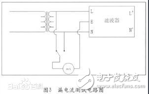
Leakage current is the current flowing between the phase and neutral lines and the filter housing (ground) at 250VAC. It mainly depends on the value of the grounding capacitor (common mode capacitor). The larger common mode capacitor CY can increase the insertion loss, but it causes a large leakage current. The test circuit for leakage current is shown in the figure:

Leakage current performance test
Withstand voltage
To ensure the performance of the power supply filter as well as the equipment and personal safety, a withstand voltage test must be performed. The withstand voltage test is a test under extreme working conditions. If the CX capacitor's withstand voltage is not good, it may be broken down when a peak surge voltage occurs. Its breakdown does not endanger personal safety, but it can result in loss of filter function or performance degradation. In addition to meeting the ground leakage current requirements, CY capacitors have sufficient safety margins for electrical and mechanical performance to avoid breakdown short circuits under extreme environmental conditions. The pressure resistance between the line and the ground is of great significance for the protection of personal safety. Once the insulation protection measures of the equipment or device fail, it may cause casualties.
Performance evaluation
The EMI power filter is considered to be the most rated voltage and current value, withstand voltage performance, and leakage current. The most important evaluation performance is the insertion loss performance of the filter.
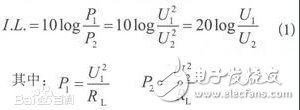
The EMI power filter suppresses the interference noise with the insertion loss I. L. (InserTIon Loss) to measure. The insertion loss is defined as the ratio of the power P1 transmitted from the noise source to the load and the power P2 transmitted from the noise source to the load when there is no filter access, expressed in dB (decibel).

Performance evaluation
Frequency domain test
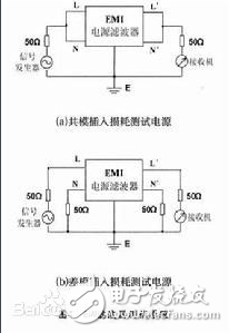
1. Standard test for insertion loss
It is specified in the standard measurement method to test its insertion loss characteristics in a system of any resistance between 50 Ω and 75 Ω.
2 . Insertion loss loading test
In EMI filter products, due to the use of unsuitable materials, the common mode choke cannot guarantee that full symmetry will lead to saturation of the magnetic ring, and the parasitic differential mode inductance may also cause saturation of the magnetic ring, making the actual use of the filter. There is a big gap between the situation and the data provided by the manufacturer, so the load test must be applied to the filter.

Standard test for insertion loss
3. Time domain testing of EMI filters
In general, for EMI power filters we only care about its general performance and frequency domain rejection. For the EMI signal line filter, since the transmission line itself generates certain electromagnetic interference, the test signal will inevitably produce a certain attenuation. At this time, we have to test the performance of the time domain transmission.
Using a 50 kHz square wave to filter the filter pin with a capacitance of 8000 pF, it is found that the rising and falling edges of the time domain have significant changes. In the frequency domain, after filtering, the high frequency components of the square wave signal are filtered out.
For the same filter pin, the higher the frequency of the square wave, the greater the harmonic signal will be attenuated by the filter pin, and the longer the wave rise and fall time of the square wave will be. Similarly, for the same frequency waveform, the larger the filter capacitance value is, the more the square wave rise time is slowed down by the filter pin.
4. EMI filter insertion loss automatic test system design
As the content of EMC testing becomes more and more complex, the test workload increases dramatically, and the requirements for test equipment in terms of function, performance, test speed, and test accuracy are also increasing. In this case, the traditional manual test has been difficult to meet the requirements. The national standard (GB) and the national military standard (GJB) require that the electromagnetic compatibility test must be performed automatically, and there are strict requirements for data post-processing. Therefore, the development of EMC automatic testing has become an inevitable path. The automatic test system established in this paper uses virtual instrument technology, based on the signal source-spectrum analyzer to insert and damage the EMI power filter.
Power filter test1. Subject: Specification of acceptance requirements, projects, methods and sampling plans for power filters.
2. Conventional inspection items
2.1 Appearance and logo
2.1.1 Technical requirements: The appearance surface should be clean and free of scars and rust and dirt. The insulation of the enameled wire is well-formed and has no obvious mechanical damage. The structure is firm and loose, the marking is complete and correct, and the pins are not obviously oxidized.
2.1.2 Inspection method: Visual method.
2.2 Size
2.2.1 Technical requirements: The dimensions of the external structure shall comply with the drawing requirements specified in the product specification and the relevant supplementary EDE regulations of our company.
2.2.2 Inspection method: The measurement with the caliper is combined with the trial insertion method of the printed board, and the test insertion has no obvious high foot phenomenon.
2.3 inductance and winding inductance deviation
2.3.1 Technical requirements: Meet the requirements specified in the product specification.
2.3.2 Inspection method: Test with the LCR instrument according to the specified test conditions, and subtract the inductance of the two windings to obtain the deviation of the unbalanced inductance of the winding.
2.4 DC copper resistance
2.4.1 Technical requirements: Meet the requirements specified in the product specification.
2.4.2 Test method: Test with DC low resistance tester.
2.4 Withstand voltage, insulation resistance
2.4.1 Technical requirements: Performed in accordance with the requirements specified in the technical agreement or product specification.
2.4.2 Inspection method: Test with a pressure/insulation resistance tester, pay attention to setting the appropriate gear position and the specified leakage current. Operators follow safe operating procedures to ensure personal safety.
3. Test items: Execute according to the “General Test Specificationsâ€.
4. Inspection failure classification
Class 4.1A fails: No EDE, mixed gauge, insufficient inductance, excessive inductance deviation of the winding, excessive copper resistance, inconsistent voltage, and poor insulation resistance.
Class 4.2B is unqualified: the material list does not match, the identification is wrong, there is no identification or incompleteness, the identification is not identifiable, and the size is out of tolerance.
4.3 Class C unqualified: Incoming material overdue, slightly out of size does not affect the use, the logo is vague but identifiable, poor appearance, poor packaging.
5. Record data
5.1 Project: Inductance, winding inductance deviation, DC copper resistance, withstand voltage, insulation resistance.
6.1 The routine inspection project adopts a normal sampling in GB/T2828.1-2003, the general inspection level II, the receiving quality limit AQL value is divided into:

The number of judgments for Class A failures of conventional inspection items is unified as: Ac=0, Re=1;
Relaxation test: a normal sampling in GB/T2828.1-2003, general inspection level I;
Strict inspection: a normal sampling in GB/T2828.1-2003, the general inspection level;
6.2 Special inspection items and routine test items shall be carried out according to the self-scheduled sampling plan;
Relaxation test: no
Strict inspection of special inspection items: The number of samples is doubled and the number of judgments is unchanged.
Routine test of routine test items: According to test specifications.
6.3 Transfer rules:
6.3.1 The quality analysis will be decided according to the quality of the inspection and production market feedback.
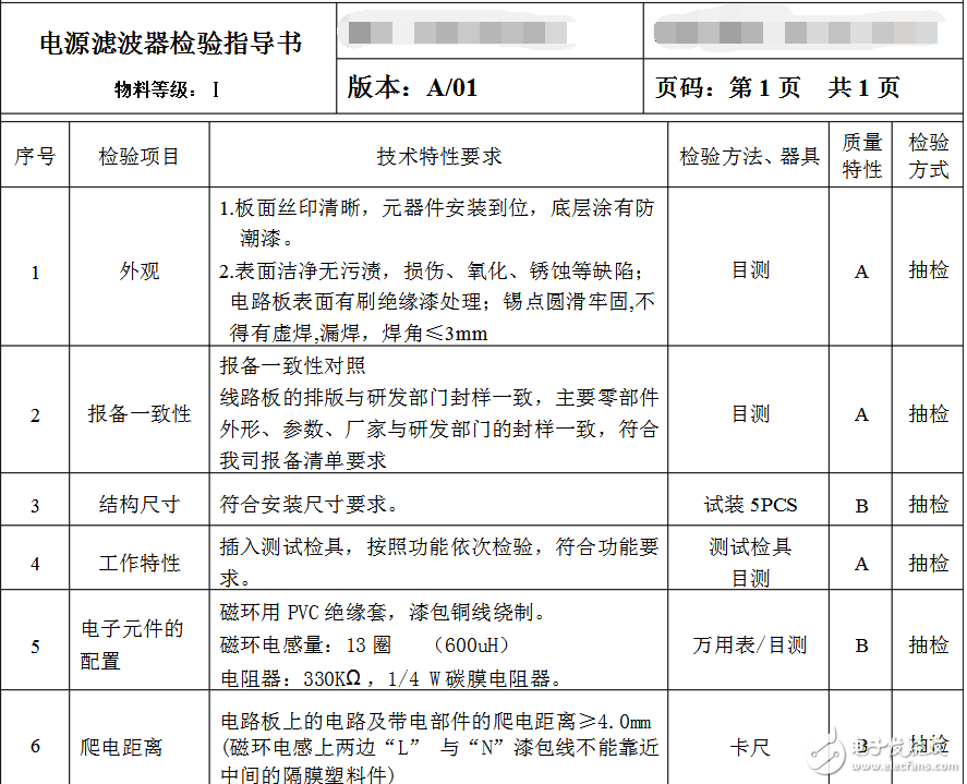
Power filter check form
Automotive Shoes And Clothing Staple
Upholstery Industrial Staple,Shoes Staple Nail,22 Gauge 71 Series Staple,Custom Shoes Staple
Zhejiang Best Nail Industrial Co., Ltd. , https://www.beststaple.com