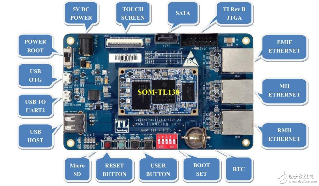
Overview:
MII (Media Independent Interface or Media Independent Interface) is an Ethernet industry standard defined by IEEE-802.3. It includes a data interface and a management interface between MAC and PHY.
The data interface includes two separate channels for the transmitter and the receiver, each with its own data, clock, and control signals. The MII data interface requires a total of 16 signals.
The management interface is a dual signal interface: one is the clock signal and the other is the data signal. Through the management interface, the upper layer can monitor and control the PHY. MII (Management Interface) only has two signal lines.
MII standard interface is used to connect Fast Ethernet MAC-Block and PHY. Indicates that any type of PHY device can work without redesigning or replacing the MAC hardware. The MII-equivalent interfaces that operate at other rates are: AUI (10M Ethernet), GMII (Gigabit Ethernet), and XAUI (10-Gigabit Ethernet).

The MII bus specified in IEEE 802.3 is a universal bus for connecting different types of PHYs to the same network controller (MAC). The network controller can use the same hardware interface to connect with any PHY.
MII related interface introduction:
Ethernet media interfaces are: MII RMII SMII GMII
All these interfaces come from the MII. The MII (Medium Independent Interface) means that it does not take into account that the media is copper shafts, optical fibers, cables, etc., because these media processing related work has a PHY or a chip called MAC. .
The MII supports 10M and 100M operations. An interface consists of 14 lines. Its support is still flexible, but it has a disadvantage because it uses too many signal lines for a port. If an 8-port switch is used, To 112 lines, 16 ports will use 224 lines. To 32 ports, 448 lines will be used. Generally speaking, this interface is used as a switch. It is not realistic, so the modern switch will be used for other purposes. Some of the standards that have been simplified from the MII, such as RMII, SMII, GMII, etc.
The RMII is a simplified MII interface. It uses twice as many signal lines as the MII interface for data transmission and reception, so it generally requires a 50-megabit bus clock. RMII is generally used in multi-port switches. Instead of having to receive and send two clocks per port, all data ports use one clock for all ports. This saves a lot of ports. One port of the RMII requires 7 data lines, which is twice as much as that of the MII, so the switch can access multiple data ports. Like the MII, the RMII supports bus interface speeds of 10 megabits and 100 megabits.
SMII is a media interface proposed by Cisco. It has fewer signal lines than RMII, and S means serial. Because it uses only one signal line to transmit data, and one signal line to receive data, it has a high clock frequency to meet the requirement of 100 on the clock, reaching 125 megabits. Why 125 megabytes is because of the data? The line will send some control information. SMII only uses four signal lines for one port to complete the transmission of 100 signals, which is almost twice as many signal lines as RMII. SMII's support in the industry is very high. In the same way, all ports send and receive data with the same external 125M clock.
The GMII is a Gigabit Ethernet MII interface. This also has a corresponding RGMII interface, which represents a simplified GMII interface.
MII working principle:"Media independence" indicates that any type of PHY device can work without redesigning or replacing the MAC hardware. Includes two separate channels for the transmitter and receiver, respectively. Each channel has its own data, clock, and control signals.
The MII data interface requires a total of 16 signals, including TX_ER, TXD, TX_EN, TX_CLK, COL, RXD, RX_EX, RX_CLK, CRS, RX_DV, and the like.
The MII transmits data bidirectionally in 4 nibbles at a clock rate of 25 MHz. Its working rate can reach 100Mb/S.
The MII management interface is a dual signal interface, one is a clock signal and the other is a data signal.
Through the management interface, the upper layer can monitor and control the PHY. The management is performed by reading and writing registers of the PHY using the SMI (Serial Management Interface) bus.
Some of the registers in the PHY are defined by the IEEE so that the PHY reflects its current state into registers. The MAC continuously reads the PHY's status register via the SMI bus to know the current state of the PHY, such as connection speed, duplex Ability and so on.
Of course, the SMI can also set the PHY register to achieve the control purpose, such as the flow control of the open and close, auto-negotiation mode or the mandatory mode.
Whether it is the physically connected MII bus or the SMI bus or the PHY's status registers and control registers are all IEEE compliant, different companies' MACs and PHYs can work in concert. Of course, in order to match the unique features of the PHYs of different companies, the driver needs to be modified accordingly.
The PHY is a physical interface transceiver that implements the physical layer. Including MII/GMII (medium independent interface) sublayer, PCS (physical coding sublayer), PMA (physical media attachment) sublayer, PMD (physical medium correlation) sublayer, MDI sublayer. 100BaseTX uses 4B/5B encoding.
When the PHY sends data, it receives data from the MAC (for the PHY, there is no concept of a frame, for it is data regardless of the address, data or CRC), and an error of 1 bit per 4 bits is added. The code then converts the parallel data into serial stream data, encodes the data according to the encoding rules of the physical layer, and then sends the data out as an analog signal. The process of receiving data is the reverse.
The PHY also has an important function to implement some of the functions of CSMA/CD.
It can detect whether there is data transmission on the network. If there is data waiting in the transmission, once the network is detected to be idle, it will wait for a random time and send the data out. If two happen to send data at the same time, that would create a conflict. At this point, the conflict detection agency can detect the conflict and wait for a random time to resend the data. This random time is very precise and not a constant. The random times calculated at different times are different, and there are multiple algorithms to cope with the second collision between the two hosts with low probability of occurrence.
The communication rate is negotiated by both parties. The result of the negotiation is the maximum speed and the best duplex mode that can be simultaneously supported by the two devices. This technology is called Auto NegoTIaTIon or NWAY.
The isolation transformer sends the differential signal from the PHY to the differential-mode coupled coil to enhance the signal and is coupled to the other end of the connected network cable by the electromagnetic field conversion.
In RJ-45, 1 and 2 transmit data, and 3 and 6 receive data.
The new PHY supports the AUTO MDI-X function and also requires isolation transformer support. It can realize the automatic exchange of the functions of the transmission signal lines on the 1 and 2 and the reception signal lines on the 3 and 6 of the RJ-45 interface.
GMII Interface Introduction:GMII (Gigabit MII), GMII uses 8-bit interface data, working clock 125MHz, so the transmission rate up to 1000Mbps. It is also compatible with the 10/100 Mbps operating mode specified by MII.
The GMII interface data structure conforms to the IEEE Ethernet standard. See IEEE 802.3-2000 for the definition of this interface.
Transmitter:
â—‡ GTXCLK - Gigabit TX. Signal clock signal (125MHz)
◇ TXCLK——10/100M signal clock
â—‡ TXD[7..0] - data being sent
â—‡ TXEN - Transmitter Enable Signal
â—‡ TXER - Transmitter Error (used to destroy a packet)
Note: At the Gigabit rate, the GTXCLK signal is provided to the PHY and the TXD, TXEN, and TXER signals are synchronized with this clock signal. Otherwise, at the 10/100M rate, the PHY provides the TXCLK clock signal, and other signals are synchronized with this signal. Its operating frequency is 25MHz (100M network) or 2.5MHz (10M network).
receiver:
RX RXCLK - receive clock signal (extracted from received data and therefore not associated with GTXCLK)
RX RXD[7..0] - receive data
RX RXDV - effective reception data indication
RX RXER - Receive data error indication
COL COL - Collision Detection (Half Duplex Only)
Management configuration
â—‡ MDC - Configure Interface Clock
â—‡ MDIO - Configure Interface I/O
The management configuration interface controls the characteristics of the PHY. The interface has 32 register addresses, each with 16 bits. The first 16 of them have been specified in "IEEE 802.3, 2000-22.2.4 Management FuncTIons" and the others are specified by the devices themselves.
RMII Introduction:RMII: Reduced Media Independant Interface is a simplified media independent interface; it is one of the standard Ethernet interfaces and has fewer I/O transmissions than the MII.
Questions about RMII and MII ports
The RMII port uses two wires to transmit data.
The MII port uses 4 wires to transmit data.
GMII uses 8 lines to transmit data.
MII/RMII is just an interface. For 10M line rate, the speed of MII is 2.5M, and RMII is 5M; for 100M line speed, the speed of MII is 25M, and RMII is 50M.
MII/RMII is used to transmit Ethernet packets. The MII/RMII interface is 4/2bit. In Ethernet PHYs, it is necessary to perform serial-to-parallel conversion, codec, etc. before transmission can be performed on twisted pair cables and optical fibers. Follows IEEE 802.3(10M)/IEEE 802.3u(100M)/IEEE 802.1q(VLAN).
The Ethernet frame format is: Preamble + Start Bit + Destination Mac Address + Source Mac Address + Type/Length + Data + Padding (OpTIonal) + 32bit CRC
If there is a Vlan, add 2 bytes of Vlan Tag after the type/length. Among them, 12 bits represent the Vlan Id, and the other 4 bits represent the data priority!
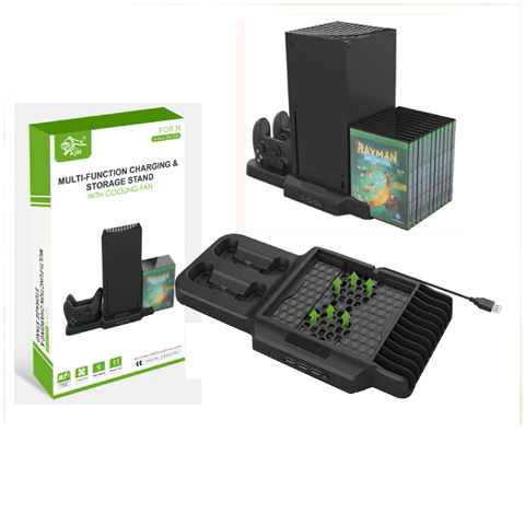
Xbox Series X Vertical Stand Cooling Fan
|
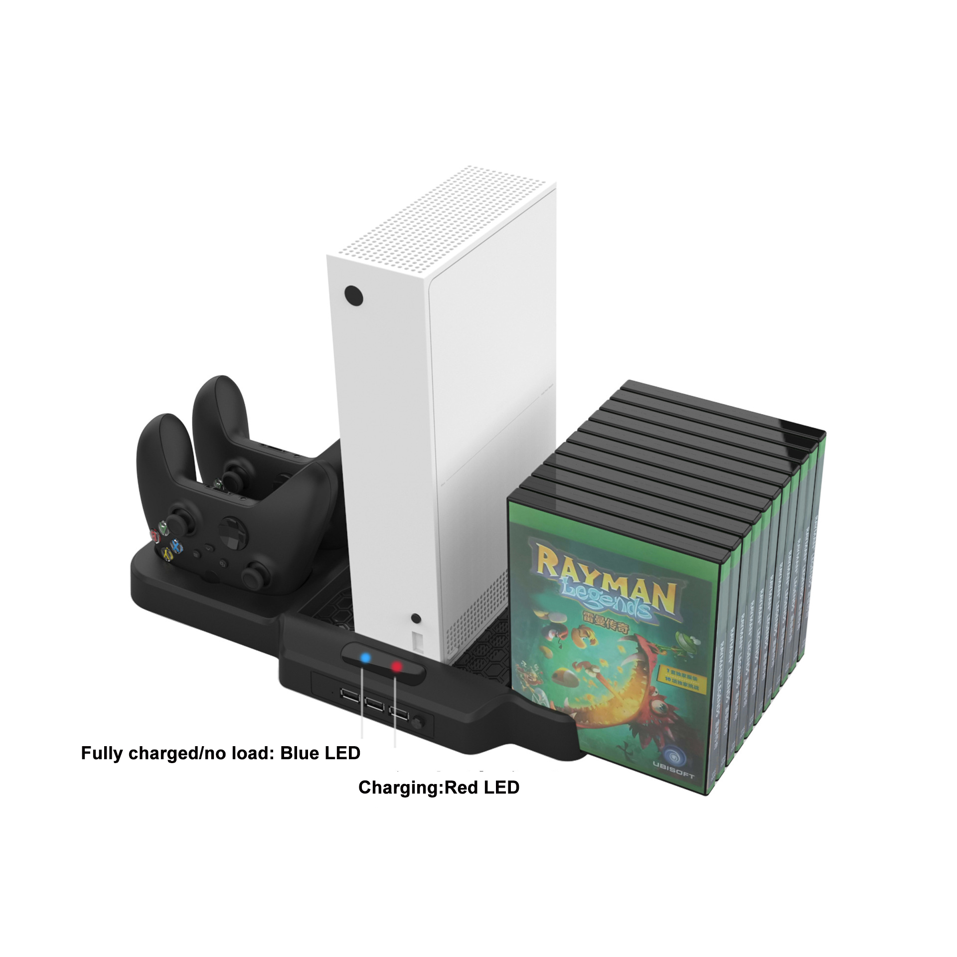
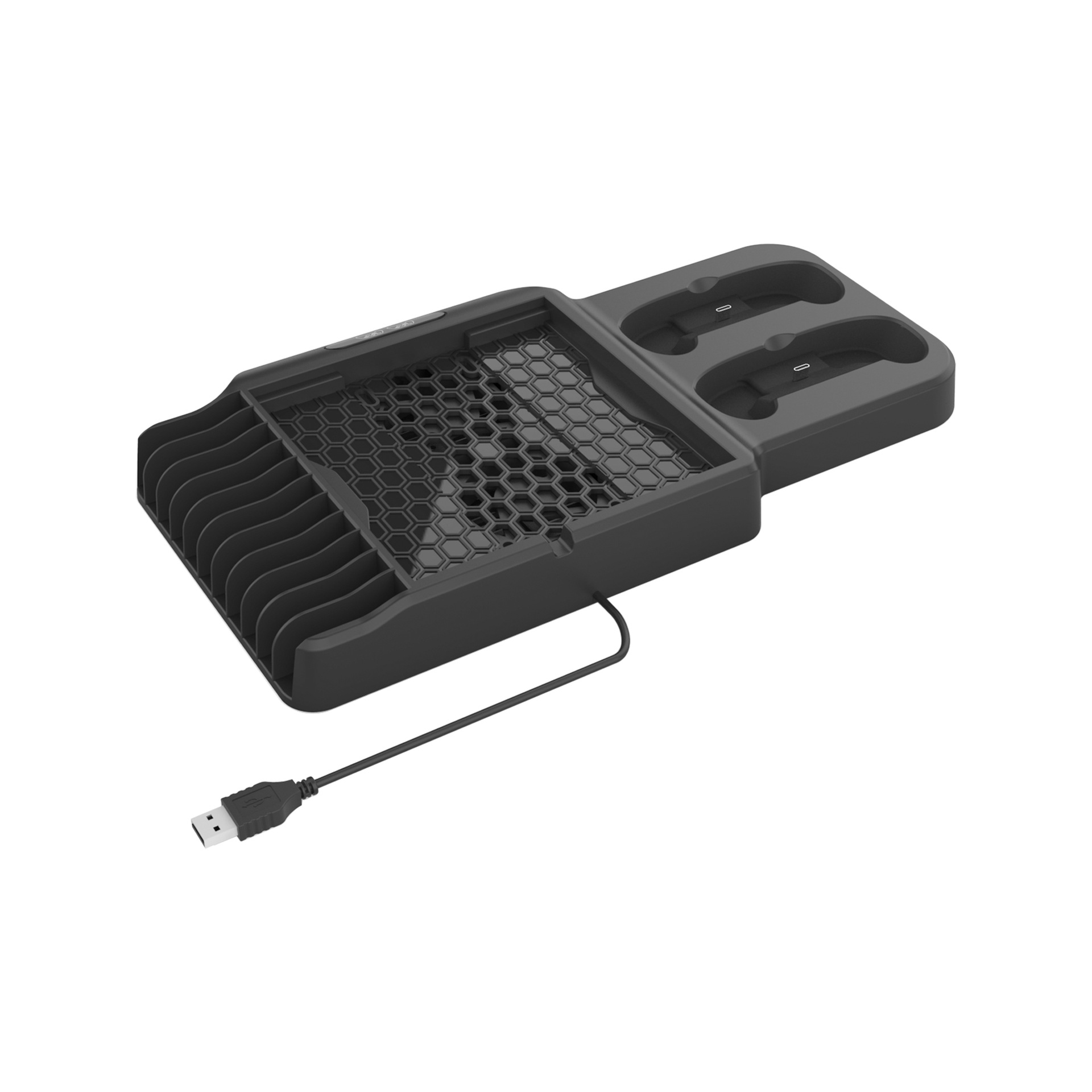
Design for X-box SX / SS game console and controller . Including 3 USB hubs,which can expand USB functions and easy to use
*Includes two charging docks, which can charge two X-box SX / SS controllers at the same time.
*With charging indicator function.When the indicator light is blue, it means it is fully charged or empty; if the indicator light is red, it means it is charging.
*Includes two cooling fans, 3000RPN, with a power button, which can quickly and effectively cool the x-box SX/SS game console. *The bracket can hold up to 11 game disc boxes. |
|
|
Product Name
|
Vertical Stand for Xbox Series X Game Console with 3USB BUB
|
|
weight
|
575g
|
|
Input
|
DC5V1A
|
|
Output
|
500mA
|
|
Product color
|
Black
|
|
Product size
|
20.5*4*36.3cm
|
|
OEM/ODM
|
warmly welcome
|
|
Advatage
|
100 QC test before shipping
|
|
Delivery Method
|
DHL,TNT,UPS , FEDEX ETC
|


Xbox Series X Vertical Stand Cooling Fan,Xbox Series X Vertical Stand,Xbox Series X Cooling Fan Station,X- Series X Cooling Fan
Shenzhen GEME electronics Co,.Ltd , https://www.gemesz.com