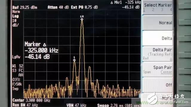
At that time, testing whether an amplifier is self-excited, the main method is to connect the spectrum analyzer to the output terminal, and the input terminal converts three kinds of loads (open circuit, short circuit, load) to see if there is self-excitation on the spectrum analyzer. This test is required at both normal and low temperatures. If you are self-excited at room temperature, you are lucky; if you don't get cold at room temperature, you are in trouble.
When I first joined the work, the main work direction was low noise design. At the beginning, I will listen to my old colleagues. When I encounter self-excitation, it will be very troublesome. Because it takes a lot of time to debug, I need to eliminate the self-excitation phenomenon under the premise of ensuring the performance inside the belt.

At that time, testing whether an amplifier is self-excited, the main method is to connect the spectrum analyzer to the output terminal, and the input terminal converts three kinds of loads (open circuit, short circuit, load) to see if there is self-excitation on the spectrum analyzer. This test is required at both normal and low temperatures. If you are self-excited at room temperature, you are lucky; if you don't get cold at room temperature, you are in trouble. The first step is to see if you can reproduce the self-excited phenomenon at room temperature by changing the external input load. If it doesn't work, you have to blindly adjust it. Just open the thermostat, then put the amplifier inside, and then freeze it, then pull it out from the hole, then quickly debug, and then put it back into the incubator to see if it is self-exciting. This step may need to be repeated many times to eliminate the self-excitation phenomenon.
By the time I started to have the opportunity to design an amplifier, I found that this method was limited by reading the literature. Because the amplifier requires any load external to the input (ie, all impedance values ​​on the entire Smith chart), it needs to be self-excited to be absolutely stable. The so-called absolute stability means unconditional stability, that is, the amplifier does not self-excite regardless of the load at the input end. But now only three loads are used above, so I always think that the self-excited amplifiers tested by this method are not necessarily absolutely stable.

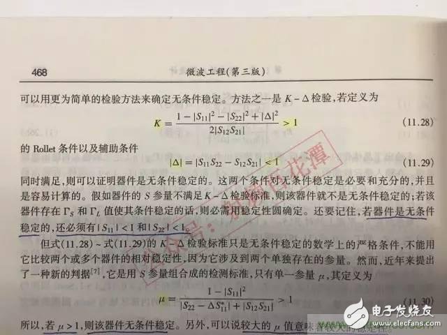
In fact, in the literature [1], in recent years, a new discriminating basis, u factor, is a necessary and sufficient condition for the stability of the amplifier. When it is greater than 1, the amplifier is absolutely stable when its value is less than 1. At the time, the amplifier is unstable. Moreover, the value of the value is also related to the strength of the stability. The larger the stability, the stronger the stability (the K factor does not have this characteristic, and the K factor needs to cooperate with the delta, which is the necessary and sufficient condition for the absolute stability of the amplifier).
Fortunately, both the simulation software and the test instrument have measurements of this parameter. During the simulation and testing process, as long as u is greater than 1, the amplifier will never be self-excited.
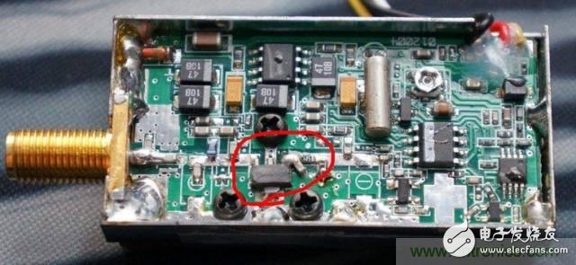
At that time, my master asked me to design an amplifier whose input was finally connected to the feed point of the antenna to form an active antenna. At that time, Master gave me a circuit that I had used on other products. There was no problem. Let me follow this circuit drawing. I simulated the circuit with simulation software and found that the u factor has a frequency less than one outside the band. At that time, I also specifically asked Master to confirm that this circuit is not self-exciting. At that time, I thought, maybe the simulation software is not allowed.

Later, after the product was processed, there was no problem in the in-band performance. After testing according to the previous three-load method, there was no self-excitation phenomenon, and it was given to the antenna personnel for integration. The next day, the antenna crew came over and said to me, self-excited. Going a trip, the cable connected to the antenna and the amplifier is self-excited, and the frequency is just at the time of simulation. The frequency factor with the u factor is less than 1, but the cable length is changed and the self-excitation phenomenon disappears. At that time, I thought, God is not thin to me, so I have the opportunity to verify theoretical knowledge. Then, the matching circuit is adjusted on the simulation software, and the u factor is adjusted to be greater than 1 in the entire frequency band, and then the amplifier circuit is modified according to the matching simulation value, and the self-excitation phenomenon disappears.
Therefore, in fact, the u factor is a very intuitive way to judge whether the amplifier is likely to be self-excited, and now the simulation software and the vector network have this measurement parameter, which is very convenient, so that we do not need to talk about "self-excited" color change.
9V Dc Adapter,Interchangeable Plug 9V 1A Power Adapter,9V 1A Power Adapter,Ac Dc Adapter 9V 1A
ShenZhen Yinghuiyuan Electronics Co.,Ltd , https://www.yhypoweradapter.com